Festive Opening Hours
Thank you for your business in 2025! Find key information on our operational hours over this holiday season
Thank you for your business in 2025! Find key information on our operational hours over this holiday season

Explore our dedicated sector pages to find expert insight, real customer stories and the solutions built to meet your unique needs.


%20x%20210%20(h)/December%202025/HP1225_UK_620x413px_HP_FP01_Dymo_Flag.jpg)
Label maker kit with fast formatting keys, QWERTY keyboard & 20+ ways to format text - includes 3x tapes.
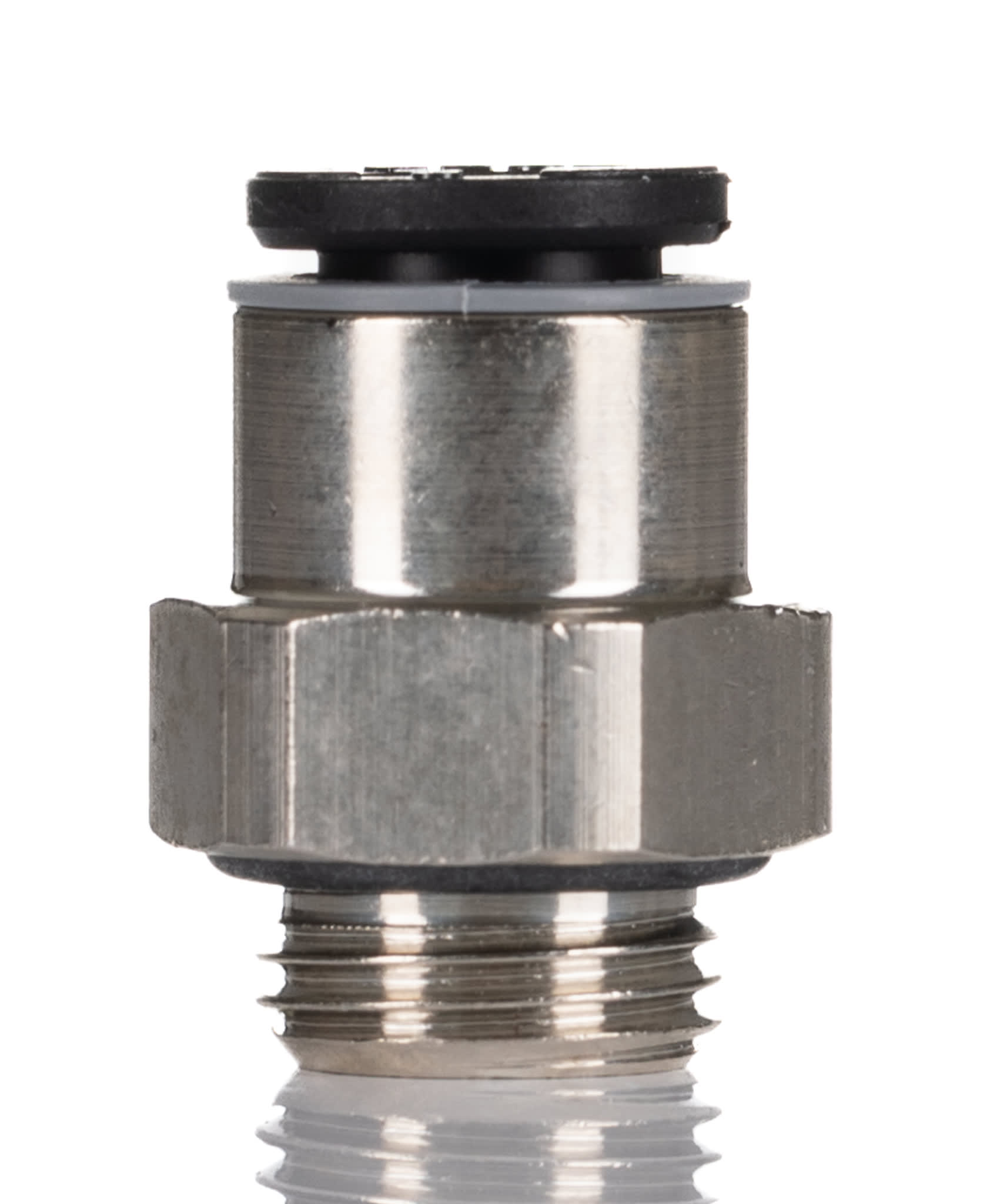
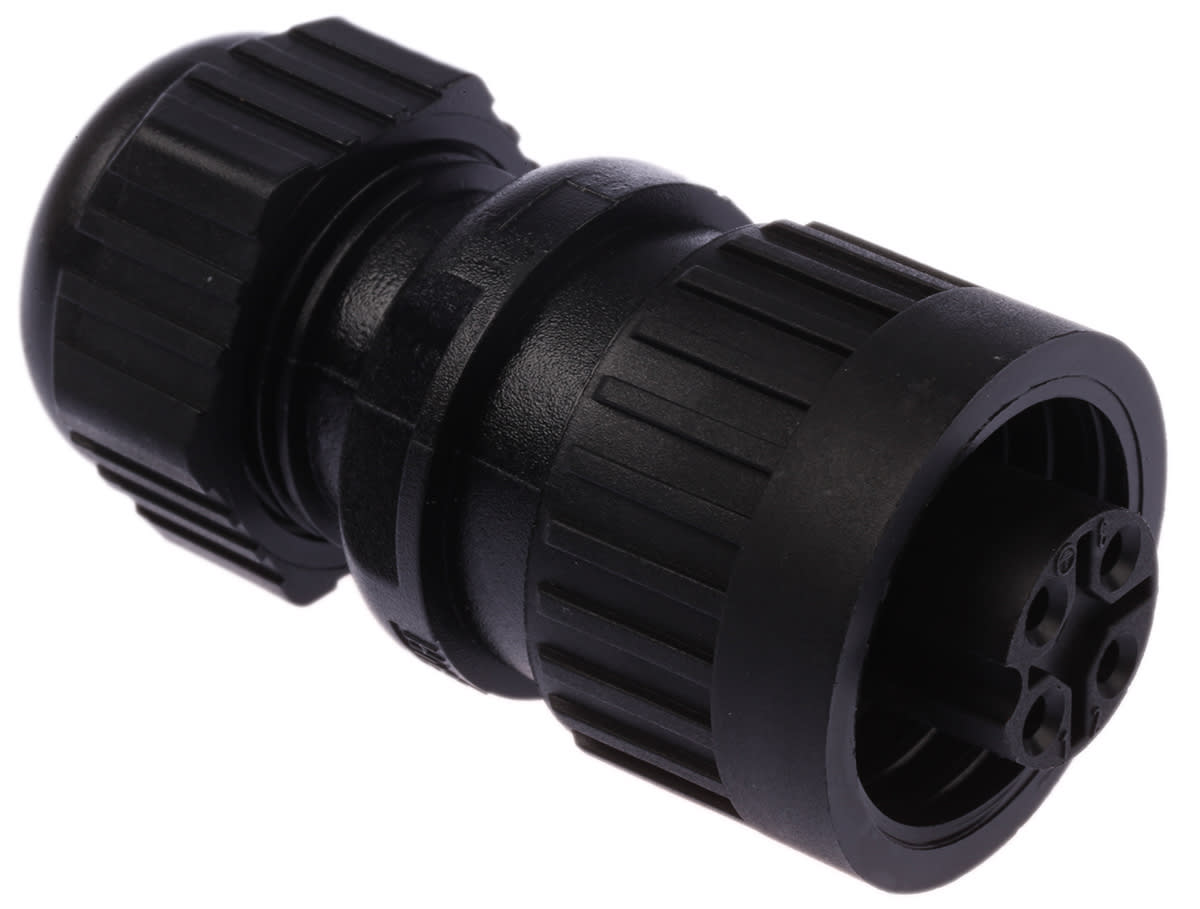
%20x%20210%20(h)/December%202025/HP1225_UK_620x413px_HP_FP02_Molex.png)
The Mini-Fit family offers Board-to-Board, Wire-to-Board & Wire-to-Wire configurations up to 13.0 Amps.
%20x%20210%20(h)/December%202025/HP1225_UK_620x413px_HP_FP02_Brady.jpg)
Handles any ID challenge with 110+ label types (wraps, sleeves, etc) for industrial or commercial use.
%20x%20210%20(h)/December%202025/HP1225_UK_620x413px_HP_FP04_Dewalt.jpg)
A lightweight, ergonomic hammer drill with 2x li-ion batteries giving a mix of high-performance & runtime.