- Published 11 Jan 2023
- Last Modified 4 Sept 2023
- 10 min
The Guide to Hall Effect Sensors

This guide is part of our Industrial Automation hub where you can discover more about AI, automation and control.
What is a Hall effect sensor?
Named after the American physicist Edwin Hall, who discovered that electricity and magnetism can work together to move objects, Hall effect sensors use this principle to convert magnetically encoded information into electrical signals.
These devices have a range of applications, with Hall effect sensors often used in automotive systems to sense position, distance and speed. These clever devices are used in various fields, but perhaps most notably in anti-lock braking systems (ABS), and internal combustion engines to assist with ignition timings.
This guide will go through everything you need to know about the Hall effect sensor, including the science behind the device, the applications for this sensor, and how to take Hall effect sensor measurements.
First though, it is important to understand how this piece of equipment works.
How do Hall effect sensors work?
When an electric current flows through any material, the electrons within the current naturally move in a straight line, with the electricity creating its own magnetic field as it charges.
If the electrically-charged material is placed between the poles of a permanent magnet, instead of moving in a straight line, the electrons will instead deviate into a curved path as they move through the material. This happens because their own magnetic field is reacting to the contrasting field of the permanent magnet.
As a result of this new curved movement, more electrons are then present at one side of the electrically-charged material. Through this, a potential difference (or voltage) will then appear across the material at right angles to the magnetic field, from both the permanent magnet and the flow of the electric current.
So, how does a Hall effect sensor work?
Using semiconductors (such as silicon), Hall effect sensors work by measuring the changing voltage when the device is placed in a magnetic field. In other words, once a Hall effect sensor detects that it is now in a magnetic field, it is able to sense the position of objects.
Hall effect sensors and magnets
Magnets are intrinsic to Hall effect sensors, which are activated by the presence of an external magnetic field. The device is then able to sense as an object moves either closer or further away, just through the differing strengths of the magnetic field.
As an example, if a Hall effect sensor was placed in a door frame and a magnet on the door, the sensor would be able to detect when the door is open or closed through the presence of the magnetic field. All magnetic fields have two important characteristics. Firstly, what is called a ‘flux density’, which refers to the amount of magnetic flow passing through a unit area, and secondly, all magnets feature two polarities (the North and South poles).
The output signal that comes out from a Hall effect sensor represents the density of a magnetic field around the device. Hall effect sensors have a preset threshold, and when the magnetic flux density exceeds this limit, the device is able to detect the magnetic field by generating an output called the ‘Hall Voltage’.
Hall effect sensors all have a thin piece of semiconductor material inside them, which passes a continuous electrical current through itself to generate a magnetic field. When the device is placed near an external magnet, the magnetic flux exerts a force on the semiconductor material. This force causes a movement of electrons, creating a measurable Hall voltage and activating the Hall effect sensor.
The output Hall voltage from the Hall effect sensor is directly proportional to the strength of the magnetic field passing through the semiconductor material. Often, this output voltage is quite small - equal to only a few microvolts - with many Hall effect devices including built-in DC amplifiers, alongside logic-switching circuits and voltage regulators, which are there to help improve the sensitivity (and therefore effectiveness) of the device.
Hall effect sensor types
There are two types of Hall effect sensors: Devices with linear (or analogue) outputs, and those that have digital outputs. Analogue sensors use a continuous voltage output that increases within a strong magnetic field and decreases in a weaker field.
With linear output Hall effect sensors, as the strength of the external magnetic field increases as the device comes into contact with the magnet, the output signal increases in parallel until it reaches the limits imposed by the power supply.
The digital output device, conversely, has a ‘Schmitt trigger’, which is a bistable circuit that steadily increases and decreases the output when the voltage rises and falls to different thresholds.
Thanks to the Schmitt trigger, when the magnetic flux passing through the Hall effect sensor exceeds the device’s preset value, the output from the device switches it from ‘off’ to ‘on’. As the sensor then moves in and out of the magnetic field, the built-in hysteresis in the device eliminates any oscillation of the output signal.
Digital Hall effect sensors
There are two types of digital Hall effect sensors: bipolar and unipolar, which differ depending on the type of magnetic field needed to operate them.
Bipolar digital Hall effect sensors need a positive magnetic field (which comes from the South pole of a magnet) to operate them, and use the negative field (from the North pole) to release them. Unipolar sensors only need a single magnetic South pole to both operate and release them as they move in and out of the magnetic field.
As the output drive capabilities are very small on the majority of digital Hall effect sensors, most of these devices cannot directly switch large electrical loads. Many digital sensors counter this by using an open-collector NPN transistor.
The transistor operates as a switch, shorting out the output terminal to the ground when the magnetic flux density is higher than the Hall effect sensor ‘on’ point. There is a wide range of Hall effect switches available, which are suitable for a variety of different tasks.
Hall effect sensor uses
Having explained how Hall effect sensors work, and the different types available, when are these devices used? There are various Hall effect sensor applications, with the uses for the device differing depending on how the magnet is positioned and the way it moves towards the sensor.
The types of magnet movement include: head-on, sideways, push-pull, and push-push, amongst others, with these variants changing the way the sensor picks up the magnetic field. Before looking at the different Hall effect sensor uses, it is worth looking at the two most common magnetic movements to understand how and why they work.
Head-on detection
This requires the magnetic field to be perpendicular to the Hall effect sensor, with the magnet approaching the sensor straight on. Linear sensors detect the strength of the magnetic field through the distance of the magnet in this approach. When the magnetic field is nearer, the stronger it is, leading to a greater output voltage.
Sideways detection
This is when the magnet moves across the face of the Hall effect sensor in a sideways motion. This type of movement is particularly useful for counting rotational magnets, or for detecting how fast a motor is rotating.
The differing magnetic movements offer various uses for Hall effect sensors. The most common application for these devices is to measure the presence, position and proximity of objects, in both industrial and domestic settings.
At home, you might have a Hall effect sensor in your printer, which is used to detect open covers, or when the paper needs restocking. The sideways detection movement allows Hall effect sensors to be used as rotating speed sensors, which are particularly useful to the speedometers in cars and other vehicles, as well as bicycle wheels, gear-teeth and electronic ignition systems.
Other Hall effect sensor uses include current sensors, pressure sensors and fluid flow sensors, which are often used in industrial and manufacturing processes. Hall effect sensors are also an effective, contactless way to measure DC magnetic flux in current transformers.
There are also other Hall effect sensor applications where a contactless switch is needed, such as electric air guns, go-kart speed controls, and on the triggers of electro-pneumatic paintball guns.

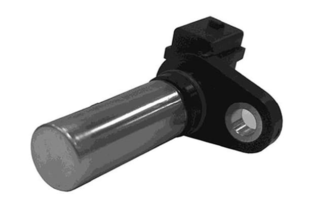
Hall effect automotive applications
In addition to these various applications, one of the main functions of Hall effect sensors is in the automotive industry, where the device has various uses, including in automotive fuel level indicators.
There are two ways that Hall effect sensors are used to measure fuel levels. Firstly, in a vertical float system, a permanent magnet is fixed to the surface of a floating object, while the sensor is fitted to the top of the tank, in line with the magnet.
After filling up your car or vehicle, the floating magnet rises to the top of the tank, bringing the magnetic field towards the sensor and increasing the Hall voltage. As the fuel levels lower, the magnet drops, decreasing the Hall voltage in parallel.
As well as measuring fuel, Hall effect sensors are commonly used to time the speed of rotating parts like wheels and shafts, and are particularly useful in various ‘tachometers’, which measure things like speed of the vehicle and RPM.
Hall effect sensors are particularly useful in conditions where things like water, vibrations, or dirt are present, which would impact upon optical and light sensors. This is why they are particularly effective in industrial applications, as magnetic fields cannot be interrupted by external factors.

Hall effect sensor smartphone
These versatile sensors have a range of applications, with Hall effect sensors in mobile phones and other mobile devices (such as tablets) used to detect flip covers, which are often equipped with magnets.
When a flip cover is closed, the magnet is brought towards the Hall sensor on your smartphone or tablet. Flip covers provide the magnetic field, which generates Hall voltage. Using a Schmitt trigger in the circuit, the mobile device is able to perform particular operations, when the Hall sensor detects this magnetic force, such as turning the screen off.
Through using a Hall effect sensor, battery life is prolonged by disabling the screen when it is covered, and can’t be used.
Hall effect sensors are used over other devices as they are extremely small, easy and cheap to manufacture, and insusceptible to wide temperature changes, which is particularly useful for phones.
Hall effect sensor measurement
While Hall effect sensors are predominantly used to detect objects and spaces, they can also be used for current measurement. As established at the beginning of this guide, the Hall Effect is based on the relationship between magnetic fields and currents, with the devices above utilising magnetic fields to create currents as an output.
By reversing this principle, you can also use a Hall effect sensor for current measurement, by passing the current to get a magnetic field.
Current sensors are an important tool for monitoring the status of equipment, detecting potential variations and ensuring that equipment is safe to use. While pressure switches, optical sensors and zero-speed switches have often been used in the past to monitor equipment, measuring the current input can provide a more accurate insight into equipment performance.
Using both a digital or linear Hall effect sensor to measure current is an effective approach, as these devices are based on the principle that for a given current flow, a proportional magnetic field is produced.
Firstly, the digital Hall effect sensor consists of three key components: the core, the Hall effect device, and signal conditioning circuitry. When the sensor is turned on and exposed to a magnetic field from the core, it produces a potential difference (or voltage) that can be measured and then amplified further into process level signals.
One major benefit of using Hall effect sensors for current measurement is that they are totally isolated from the voltage being monitored, making them a safe way to test equipment without insertion. The measurements are also accurate and repeatable on both AC and DC power, making digital Hall effect sensors an excellent choice for current measurement.
Ratiometric hall effect sensors
A variant of this is the ratiometric Hall effect sensor, which outputs an analogue voltage that is proportional to the magnetic field intensity. This type of sensor works based on the magnetic polarities, with voltage increasing with the South pole, and decreasing with the North magnetic pole.
A ratiometric Hall effect sensor is an alternative to the digital device discussed above. Instead of switching from off to on outputs, the voltage is measured proportionally to the strength of the magnetic field and magnetic polarity.
As with the digital Hall effect sensors, ratiometric devices can be used to measure the current through a wire. The higher the current, the stronger the magnetic field, and thus a higher output voltage will be measured. Both approaches offer an effective way to measure currents, and test how efficiently electrical equipment is operating.
From current measurement to pressure sensors, fluid flow sensors and object detection, Hall effect sensors and switches have a variety of uses and applications, with these versatile devices an essential part of much electrical equipment.

Popular Brands
Please click on the links below to view hall effect sensors produced by some of our most popular brands.