- Published 17 Jan 2023
- Last Modified 29 Aug 2023
- 7 min
A Guide to Bridge Rectifiers
Our bridge rectifiers guide covers what they are, what they do, and how you fit them and measure them.

A bridge rectifier, also known as a diode bridge, is a type of discrete semiconductor module product. They are primarily designed to convert AC input from mains power to a DC output, i.e. usable device power.
Bridge rectifiers are electronic components widely used in many different types of circuits and power supplies (PSUs) and are found in all manner of workplace appliances and electrical products.
There are many different types and models of bridge rectifiers for sale online in the UK. Leading manufacturers that we work with to supply diode bridge modules include ON Semiconductor, Vishay, IXYS and Semikron. Choosing the best type of rectifier for your needs will depend on the precise application you want to perform, and the parameters of the circuit and device type where it will be attached.
This guide to bridge rectifiers is designed to explain more about what these discrete semiconductors are, what they do, and why they are used.
What is a Bridge Rectifier?
A bridge rectifier is a relatively simple but important electronic component, consisting of an arrangement of at least four diodes in a bridge circuit configuration. The main defining feature of a bridge rectifier diode is that its output polarity will always be the same, regardless of the polarity at its input terminals.
A key property of the diodes in a bridge rectifier is that they only allow current to flow through them in one direction. By arranging a series of diodes in a certain way, we can therefore ensure that the current output across the bridge rectifier is unidirectional, even if it is bidirectional at the input. As such, these diode devices are known as rectifiers, because they perform a process of current rectification (converting alternating current to direct current).
They play an important role in many types of device or circuit power supplies because raw AC power flowing from a mains source periodically changes its flow direction. As such, AC power effectively results in a back and forth motion of electrons coming from the mains source into the device circuitry.
For powering almost all device types based on a standard PCB electronic circuit, this bidirectional input current needs to be converted - or rectified - into a stream of electrons all flowing in the same direction. This results in a DC power (direct current) output signal, and thus a usable output Voltage from which the device or product in question can draw stable and consistent power.
The individual component that performs this key task in a discrete circuit is typically a diode known as a rectifier; specifically, a bridge rectifier, or diode bridge. Acting as a bridge rectifier is one of the most important roles for diodes in any type of electrical circuitry. Today, semiconductor diode bridges will be found in almost any electrically powered device.
A bridge rectifier arrangement is a particularly common feature of device power supplies. They effectively act as a transformer positioned between the AC socket input and the DC output that ultimately powers the circuitry and components in the device. Bridge rectifiers are typically attached to a circuit via a two-wire AC input connection.
How Does a Bridge Rectifier Work?
You can think about current flowing across a closed powered circuit as being like water pumped from one tank to a second tank through a network of pipes. In this analogy, depending on the flow direction of the pump, one tank would be acting as the input, while the other would be the output.
Normally, reversing the pump direction would switch the entire flow direction, meaning the output tank became the input, and vice versa. If we were to attach a device such as a water wheel to one of the pipes between the two tanks, we would see it continually changing direction as we switched the flow direction of the pump back and forth.
This is also what would also happen in a simple electrical circuit if the flow direction of the input current was reversed. A rapid version of this effect is what an unmodified, or unrectified, AC power signal delivers - the flow of the alternating current continuously switches direction at very high speed.
Without a component acting as a transformer to provide a DC input, something like an LED (the water wheel, in this comparison) attached to this AC circuit would flicker on and off repeatedly with the continual shifts in the current direction. This should illustrate why many electronic devices need a direct current (DC) power source to function properly.
In practice, the easiest way to answer the question ‘how do bridge rectifiers work?’ is to refer to a simple bridge rectifier circuit diagram. A basic bridge rectifier circuit clearly shows current always flowing in the same direction after passing through an arrangement of four diodes set in a bridge circuit, regardless of the polarity at the input.
With a suitable arrangement of four or more such diodes in a bridge circuit, you end up with a unidirectional or direct current output (DC power), regardless of the input current flow direction. In addition to performing this vital current conversion role, the same principle means that bridge rectifiers are also able to provide a degree of reverse-polarity protection.
Reverse polarity occurs when leads for a DC-powered device are connected back to front, or when batteries are inserted the wrong way up. Without a circuit component such as a diode bridge configuration in place, this reversed polarity can prevent the normal functioning of the product or device and may quickly damage the rest of a circuit under load.
Diode Bridges, Graetz Bridges and the History of Bridge Rectifiers

The diode bridge circuit has been around since the 1890s when functionally similar prototypes were invented and developed almost simultaneously by two leading global electro-technicians.
Polish scientist Karol Pollak was the first to patent his design, registering a version in the UK in December 1895. Pollak’s model was also patented in Germany the following month. Despite this, German physicist Leo Graetz published his own version of a similar circuit a year later in 1897, with some slight modifications and improvements. This would ultimately become the more widely used interpretation. As a result, these components are still sometimes called a Graetz bridge or a Graetz circuit today.
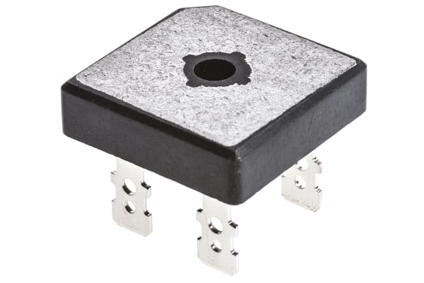
Modern diode-based bridge rectifier components are small, compact and discrete semiconductor modules that can be manufactured and bought quite cheaply. As well as being widely used in power supplies for electrical goods, they are also highly popular for use in general circuit design applications.
They are usually classified into single-phase rectifier bridge or three-phase bridge rectifier designs, and then further subdivided between uncontrolled, half-controlled (half-wave) and full-controlled (full wave) diode bridges. They are sold in various mounting configurations, with popular choices including screw mount, surface mount and through-hole designs for attachment to a PCB.
Full-Wave Bridge Rectifiers vs. Half-Wave Bridge Rectifiers
Full-wave bridge rectifiers and half-wave bridge rectifiers ultimately perform the same role, but they each do so using slightly different methods. These components are sometimes referred to as full-bridge and half-bridge rectifiers. Due to differences in the way they handle incoming AC signals, there is an observable difference in overall operating efficiency (output voltage) between these two types of diode bridges.
- Full-wave rectification happens when the diode bridge actively converts the negative component of an AC input to a positive voltage and then rectifies the entire resulting signal into DC power (pulse current). This job is handled by two power diodes in the full-wave rectifier, one for each half of the waveform
- Half-wave rectification instead takes a different approach to the first step. Rather than converting the negative Voltage component, the half-wave rectifier uses a single diode to simply remove it altogether, before the rest of the bridge arrangement transforms the remaining half of the signal to a usable DC input
This means that full-wave rectifiers are more efficient than half-wave rectifiers because the full input waveform ends up being converted and used to power the rest of the circuit. This normally also results in a smaller ripple Voltage than can be observed using a half-wave bridge rectifier arrangement.
Ripple Voltages are an unwanted effect of signal smoothing processes and will vary depending on capacitance and load on a capacitor. Lower ripple Voltage means a more stable power signature, and thus a better overall flow of steady and smooth DC power to components and devices.
Related Guides
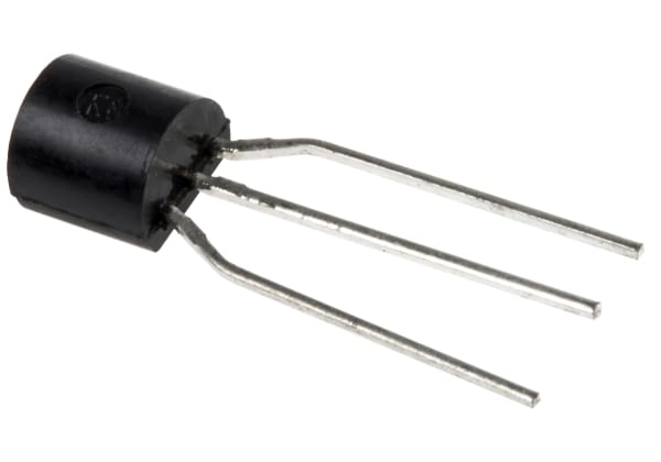
Everything You Need to Know About Bipolar Transistors
What is a bipolar transistor? Find out everything you need to know about the types and characteristics of bipolar junction transistors (BJT) in this guide.
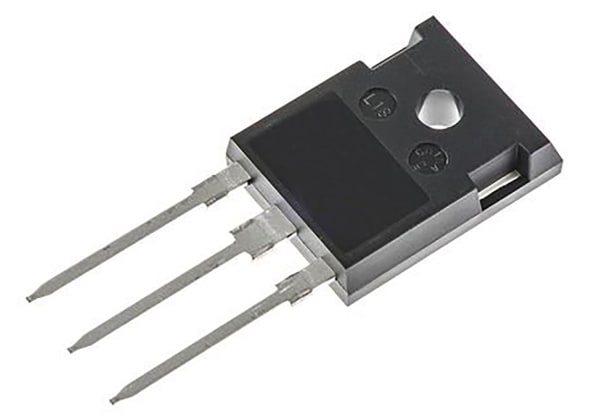
MOSFET Buying Guide - What is a MOSFET?
An easy to follow guide that explains everything you need to know about MOSFETs, including what they are and showcasing the best products available.
Related links
- Everything You Need To Know About Gas Springs and Gas Struts
- Everything You Need To Know About Thermocouples
- Everything You Need to Know About Laminators
- A Complete Guide to Rheostats
- A Comprehensive Guide to Solenoid Valves
- The Complete Guide to Stepper Motors
- The Guide to Hall Effect Sensors
- A Guide to Circular Saws