- Published 6 Jan 2023
- Last Modified 23 Jun 2025
- 12 min
The Complete Guide to Breadboards
An overview of breadboards - the best prototyping methods, hole sizes, and their impact on circuit construction and performance.

Reviewed by Jay Proctor, Technical Support Team Leader (February 2021)
In this breadboard tutorial, we’ll explore the various designs, workings and features of electronic breadboards and kits. We'll also suggest some breadboard projects for beginners looking to learn electrical circuit design and construction.
What is a Breadboard in Electronics?
The term breadboard has two common meanings today, each distinct from the other. Unsurprisingly, on this site, we’re not going to talk about a wooden surface for slicing a loaf on!
In modern electronics and engineering, a breadboard refers to a (usually) solder-free, plug-and-play platform allowing for speedy insertion and removal of electrical components in circuit-building applications.
Breadboard kits today are a very popular toolbox product among electronics professionals, enthusiasts and hobbyists alike.
What is a Breadboard Used for?
Modern electronic breadboards typically don't require soldered components. Their connections are therefore temporary, meaning users can switch them in and out quickly and easily if they need to revise or correct something.
Breadboards are used most commonly in prototyping applications. The fact that solderless breadboards don’t require circuitry components to be affixed semi-permanently to the surface of a PCB makes it much easier and quicker to manoeuvre and swap them until you achieve the desired effect. This is ideal for both experimental design and rigorous testing of electrical circuits. The hot-swappable component functionality of breadboards makes them a hugely convenient piece of equipment in the prototyping stages of circuit design and development.
As well as being considerably more economical in terms of both time and expense, the use of breadboards has the added advantage of making diagnostic and debugging work far more straightforward.
Solderless breadboards are ideal for technical analysis applications. Breadboarding a circuit allows electronics engineers to quickly replicate a real-world PCB found in an existing product or system. This can be especially useful in helping identify likely points of electronic fault or failure in a given circuit, without having to waste time and money making incremental or experimental adjustments to a fully soldered board in a complete but malfunctioning product. A single misplaced lead in a sprawling and complex circuit can cause the entire system to behave oddly (or stop working altogether). It's extremely useful to see exactly where each component pin is placed without guesswork or incorrect soldering slowing things down!
Breadboard Layout
For anyone already familiar with printed circuit boards (PCBs), the basic layout of a solderless breadboard will make sense. For those new to the format, however - and breadboards for beginners are especially popular - they can look confusing at first.
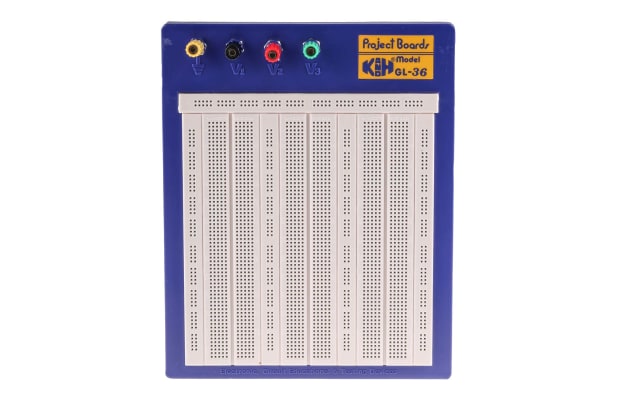
Essentially, a standard empty breadboard is a very simple piece of electronic mounting equipment. It consists of a rectangular plastic platform covered with multiple rows of small, densely packed holes.
These holes are intended for the metal contact pins (sometimes referred to as leads or legs) of various compatible electronic components to be pushed into. They make contact with conductive metal strips running around the inside of the breadboard unit.
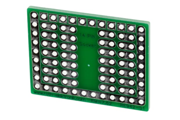
Compatibility of components is critical here: components are generally sold as two types - surface-mount or through-hole. Unlike the surface-mounted versions, through-hole components don’t need to be soldered directly to PCB faces to connect. Solderless breadboards are therefore only designed to work with through-hole components.
Breadboard schematic diagrams are commonly used in instructional manuals and educational guides. They demonstrate how to wire particular types of circuits or components to achieve a specific result. There are numerous versions of breadboarding diagram software available online, most of which do largely the same things - if you’re just starting out with electronic breadboards, find one that works for you and proceed from there.
How Does a Breadboard Work?
Solderless breadboards are:
- Suitable for both learning how to build circuits and practical testing and diagnosis applications
- Commonly used as prototyping platforms in projects to see how a circuit behaves under certain input conditions and connections
- Ideal for testing out ideas as preliminary models before building a fully soldered version on a PCB
So how do breadboards work to achieve all this, exactly? Well, running beneath the many rows of small holes for component pins are metal strips - essentially the wires of a circuit - arranged in multiple series.
These wires are what the component legs contact when they’re pushed through the holes in the breadboard surface.

The two sets of parallel wires running horizontally down each long side are the positive and negative power rails (sometimes called buses).
- Functionally, these are exactly the same as all the other wires in the unit, except each one is connected along its full length
- These buses are how external power - usually coming from an attached battery pack or similar - is fed to the breadboard and carried to all areas of a prototype circuit
- If these power rails need to be connected differently to the stock arrangement for specific types of circuits, you can buy sets of smaller detachable jumper wires to achieve this
In between the power rails, you’ll see several columns of shorter perpendicular wires, or terminal strips, occupying most of the breadboard underside. Wires in different columns and rows are generally not connected to one another, and never across either side of the wide central gap. Electronically, they’re isolated by the empty space in the middle.
Each of these terminal strips incorporates a series of five small clips, corresponding to a row of five holes on the breadboard surface. These clips grasp component leads as they're pushed through breadboard surface holes. This removes the need for soldering anything in place. Components will be held firmly enough to remain seated when the breadboard is moved around but are easy to remove with a light pull.
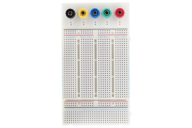
When viewing most mid-sized and larger breadboards, you’ll often find that a simple numbering and lettering system has been assigned to the various rows and columns of holes. Holes in the same row and column are usually connected by wires beneath, but not across different rows and columns. For example, holes 1A-1E will usually be connected to each other, but not to holes 2A-2E.
The alphanumeric grid system makes it easy for circuit builders to keep track of which components are connected and where. In turn, planning ahead and troubleshooting becomes simpler as the circuit grows in size and complexity. This system also provides a handy way for beginners to follow basic step-by-step instruction guides about how breadboards work when learning to construct elementary circuits using examples and exercises.
Types of Breadboards
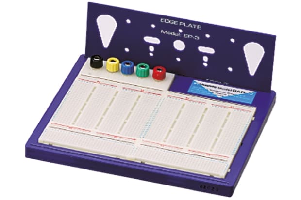
More or less all modern solderless breadboards are set up and laid out in fundamentally similar ways. That said, there are five basic breadboard configurations you're likely to find on sale from most suppliers in the UK and elsewhere. These are catalogued as Full+, Full, Half+, Half, and Mini.
The key difference between each breadboard type listed above is their overall size. However, breadboard dimensions are not universal and vary from manufacturer to manufacturer.
In each case, there may be slight differences in exactly how the different rows and columns of wire strips are connected to (or isolated from) one another, but the same general principle will apply across all the above models. For the most part, you can build any solderless prototype circuit on any breadboard size.
If a single board doesn’t provide enough physical space to create the entire circuit you want to prototype, it’s a common feature among various breadboard models to allow for linking multiple units. Where offered, this means you can connect more than one solderless board together at a time. This gives you as much space as you like for building increasingly complex breadboard projects.
How to Use Breadboards
The nature of circuit-building inherently dictates that there is no one correct method for how to use a breadboard - but there are countless incorrect ways.
Naturally, there are some fundamental rules and guiding principles to observe when designing circuits and connecting different types of components together. However, in terms of the overall breadboard project, what’s correct in any given scenario will depend largely on what you're trying to get the circuit to do.
That said, it pays to keep a few general rules of thumb in mind when using breadboards to build a functional circuit prototype. Below you’ll find a list of things to consider as you proceed:
- Remember that even simple breadboard circuits aren’t generally appropriate setups for permanent installation in any product or device. They should only be used for designing and testing circuits outside of cases and housings before moving on to a soldered version
- While you won’t typically need any tools to build a circuit on a solderless breadboard, it can be enormously helpful to have some tweezers or needle-nose pliers to hand for small components
- Be mindful of how you’re inserting component leads into the breadboard holes. Try to push them in straight down and consider trimming them if they’re not already at an optimal length. The ideal is a snug fit that allows LEDs, resistors, and other components to sit reasonably flush with the board surface
- Always pay attention to component and cable management in general, especially when arranging jumper wires. You’re highly likely to end up with a tangled, disorganised-looking board if you’re not careful about keeping them flat and routed sensibly
- Invest in a jumper wire kit to give yourself a head start with various lengths and colour-coding options at your disposal. This can prove incredibly useful as your circuits get more intricate
- Channel jumpers around, and not directly over, other components. This will make future adjustments easier
- Don't take shortcuts with breadboard wiring. Avoid wiring individual components directly to battery packs and other power supplies. Try to be disciplined and always connect via the power rails
- Consider keeping a digital multimeter handy at all times, so you can easily check connections between holes and rails if you’re uncertain about exactly how anything links up
- Remember that the configurations of holes, strips, and connections may differ from brand to brand. Basic breadboard parts and functions are the same on any type. However, it’s wise to be clear about how things link up on the specific board you’re working with if you want to avoid frustrations
Need to calculate the resistance value for parallel and series resistors? Our Parallel and Series Resistance calculator takes out the hard work and gives you the answer you need in a few clicks.
How to Set Up a Breadboard
Join Natalia, one of the student FemEng Lab members, as she takes you through a step-by-step demonstration on how to set up a breadboard. Natalia will explain the basics of breadboard components, and guide you through the process of setting up the breadboard. She will also provide tips on troubleshooting and help you become more comfortable with using breadboards.
Breadboard vs Soldering
Breadboarding and soldering are two different methods used in electronics prototyping and circuit construction. Here are some key differences between the two:
Breadboarding
- Temporary connections: Breadboarding involves creating temporary connections between components using the spring clips or holes on a breadboard. No soldering is required, making it easy to assemble and disassemble circuits for experimentation and modification
- Flexibility and reusability: Breadboards offer flexibility as components can be easily inserted and removed, allowing for rapid prototyping and testing. The same breadboard can be reused for multiple projects
- No special tools required: Breadboarding typically does not require any special tools or equipment. Components can be inserted and connected using hand pressure or jumper wires
- Limited high-frequency performance: Breadboards may introduce some additional resistance, capacitance, and inductance due to the inherent effects of the contacts and wiring. This can affect circuit performance, particularly at higher frequencies
Soldering
- Permanent connections: Soldering involves permanently joining components together by melting solder onto the component leads and circuit board pads. Soldered connections are more secure and stable compared to breadboard connections
- Better electrical performance: Soldered connections offer lower resistance, better conductivity, and improved reliability. They are less prone to loose connections, which can occur on a breadboard
- Suitable for production: Soldering is the preferred method for manufacturing electronic circuits. It provides a more robust and durable connection, suitable for long-term use
- Requires soldering equipment: Soldering requires specialised tools, including a soldering iron, solder wire, and flux. It may also involve additional equipment like a soldering station, soldering stand, and soldering fume extractor for safety purposes
- Permanent modifications: Once components are soldered onto a circuit board, they are more difficult to remove or modify compared to easily changeable breadboard connections
Both breadboarding and soldering have their advantages and are used in different stages of electronics prototyping and development. Breadboarding is commonly used for initial design, experimentation, and testing, while soldering is employed for more permanent and finalised circuit constructions. The choice between the two methods depends on factors such as the complexity of the project, the need for durability, and the desired electrical performance.
FAQs
Overall, we have explored a thorough understanding of electronic breadboard essentials. We have covered crucial topics such as breadboard usage and their underlying principles. In addition, we have covered how to effectively use electronic breadboards in various applications. By understanding the fundamentals, you are well-placed to master breadboard usage and functionality in your projects.
Related Articles
Parallel and Series Resistance Calculator
A calculator designed to help you understand the output resistance value when calculating how many resistors required in either a series or parallel circuit formation.

An Overview of Development Tools for Electronics Engineers
Unsure about development boards? This guide covers all the essentials, from what they are to the existing products and brands such as MBED boards, STM Nucleo boards, and everything in between.
Everything You Need To Know About Eurocards PCB
In our comprehensive guide we look at what Eurocards are, what types and sizes are available, as well as the different uses of Eurocards that are available on the market.