- Published 30 Jan 2023
- Last Modified 29 Aug 2023
- 6 min
Isolators & Switch Disconnectors Guide
Read our isolators and switch disconnectors guide, explaining what they do, their uses, and the different types.

Updated April 2022
What are Isolators and Switch Disconnectors?
Electricity can be dangerous. It is vital to use a reliable method of cutting off current and isolating a circuit when adjusting electrical equipment. Switch disconnectors perform this function, cutting off the electricity supply to power down a length of the electrical circuit so it can be serviced.
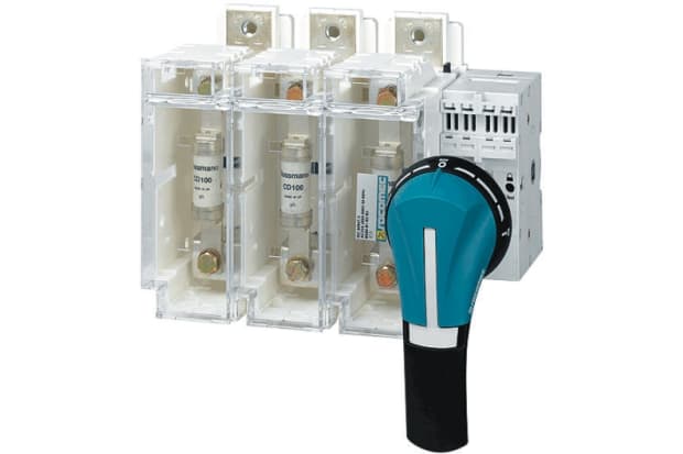
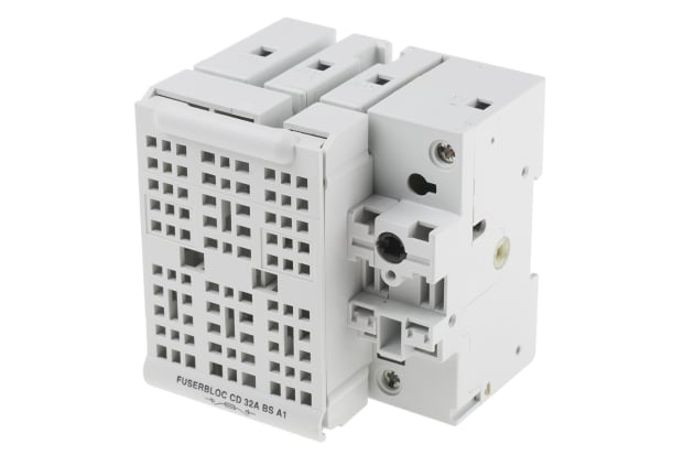
Fused switch disconnectors are a type of isolator, a standard electrical safety device, but they differ from other varieties in combining isolating and current switching functions. Fuses within their enclosures allow sections of an electrical circuit to be quickly and safely shut down and then re-energised when the required maintenance has been completed.
Isolator switches are also distinct from circuit breakers, although they have a similar function. Circuit breakers stop the flow of current to an entire circuit, while isolator switches cut off only part of the circuit.
Isolator switches are offload devices, meaning that the requisite part of the circuit is only isolated after the current has been stopped. By contrast, circuit breakers are on load, so the current continues up until the moment of the break.
It is relatively common to use both a circuit breaker and an isolator switch for additional safety in higher voltage environments. The former cuts off the current to the whole circuit and the latter then isolates a section for safe access during servicing.
Alternative Names
Switch disconnectors have a variety of alternative names. You may encounter any of the following when shopping for these essential devices:
- Isolator switches
- Isolation switches
- Power isolation switches
- Fused isolators
- Fused isolator switches
- Fused or fuse switch disconnector
- Disconnecting, disconnector or disconnect switches
- Switch fuse disconnector
What Does an Isolator Switch Do?
These switches protect engineers and electricians from the risk of electrocution. They also help to prevent damage to the circuit hardware by minimising short circuits and overcurrent, and by allowing timely maintenance. Isolators or disconnectors work by physically separating sections of a circuit - this is called an air break. Fused switch disconnectors provide an additional level of safety and certainty because these will blow, breaking the circuit, in the event of rogue current.
What are Isolators and Switch Disconnectors Used for?
All electrical equipment requires servicing and maintenance from time to time. Current protection devices such as isolators and switch disconnectors have become standard equipment and are installed in everything from domestic housing to electrical substations. They can also be attached to car batteries to protect mechanics conducting repairs.
Isolator and Switch Disconnector Types
Like most professional electrical equipment, isolator switches are available in a variety of models, designed for different uses. Some are made for alternating current (AC) and others for direct current (DC). They may be intended specifically for industrial use, with varying numbers of fuses and poles - e.g. DP isolator switches or their three-pole counterparts.
Rotary switch disconnectors feature large analogue dials for easy activation and deactivation. Meanwhile, load disconnect switches, also known as load break switches, are designed to operate at specific currents rather than within a range.
Poles
In electrical terminology, a pole is the number of circuits that a single switch can control - so a single-pole switch can control a single circuit, while a double pole (DP) isolator switch will control two. Fused isolating switches are available with several different pole configurations, from single pole to six poles, with the majority being triple pole isolators.
Isolator switches with a higher number of poles - e.g. triple pole (3P) and four-pole (4P) - are used with more complex equipment and electrical installations. TPN - triple pole neutral - devices combine a three-pole isolator with a fourth neutral pole - e.g. a circuit that returns the current to its source to ensure that it is fully utilised.
Phases
Fused isolator switches are divided into single-phase and three-phase devices. Standard models are single phase while a three-phase isolator is often preferred for very high voltage equipment. These combine three isolator switches in one, providing a higher level of safety for the electrician or engineer about to carry out maintenance work.
Amperage
The ampere (amp) is the standard international unit of electrical current. Therefore, the amperage of an electrical circuit is the strength of the current running through it.
Isolator switches are designed with maximum current ratings - i.e. the highest level of current at which they will operate safely. This can range from as little as six amps up to 200 amps, via mid-range models between 20A and 50A. Meanwhile, the fuses in fused isolators will have their own amp rating, meaning the highest level of current that can pass through the individual fuse before they blow and break a circuit. These two maximum ratings may not be the same. For example, the Socomec 3P Fused Isolator Switch offers current ratings of 63A and 100A but a fuse current rating of only 10A.
How to Wire an Isolator Switch
Like any other electrical equipment, isolator switches can be hazardous if not wired correctly. If in doubt, always consult a qualified electrician. It is also important to follow all applicable wiring regulations.
Here is how to wire an isolator switch:
- Ensure that the wiring you plan to use for the installation is fully compatible with the switch and rated for the expected current
- Make sure that the current to the relevant wires has been cut off
- Remove the previous socket (if applicable) along with any debris or dust in the wall box
- Attach the load and supply cables, wiring the internal conductors and earthing wire to the corresponding terminals according to the isolator schematic. The layout of the terminals will vary from model to model. Peel back a length of the insulation from each conductor so the screws make direct contact with the copper wiring - this is very important. Cut off any protruding strands. The earthing wire in each cable should be connected to the corresponding terminal on the switch and from there to the earthing terminal in the wall box
- Some isolator switches are supplied with a plastic gasket (mechanical seal). These should be placed between the wall at the back of the box and the device

Isolator Switch Wiring Diagram
The diagram to the right shows the wiring of a typical isolator switch.
Brands
The most popular brands and manufacturers of isolator switch include:
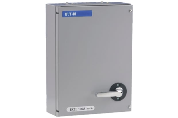
Eaton
Eaton's range of isolators and fused switch disconnectors includes the MEM and Glasgow lines. Shop now.
Socomec
With a wide range of isolators and switch disconnectors on offer, shop Socomec with RS today.
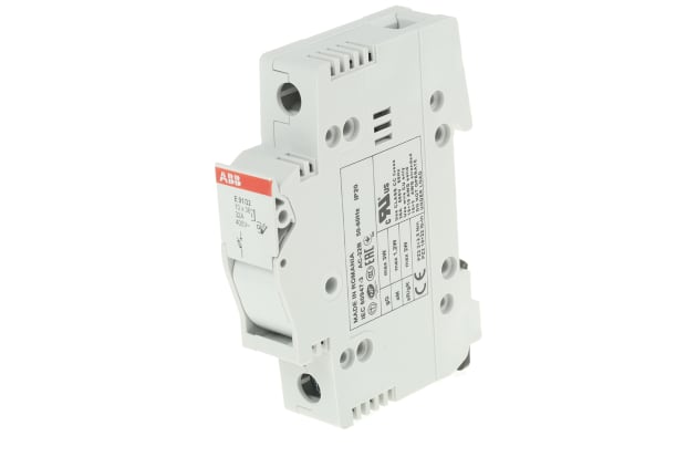
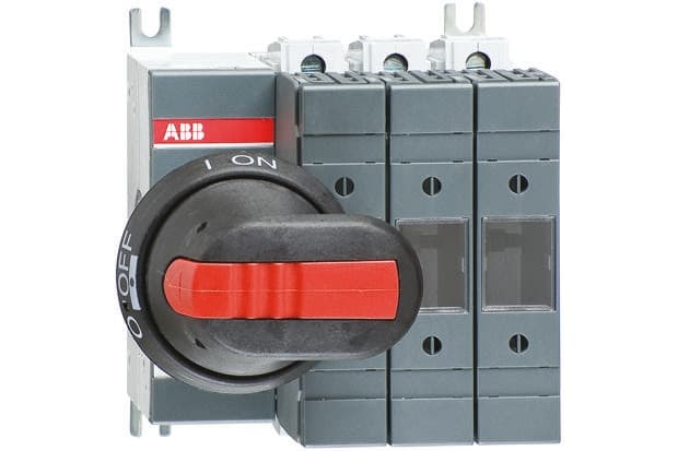
ABB
Choose between a wide range of top-quality products when you shop isolators and switch disconnectors from leading brand ABB.
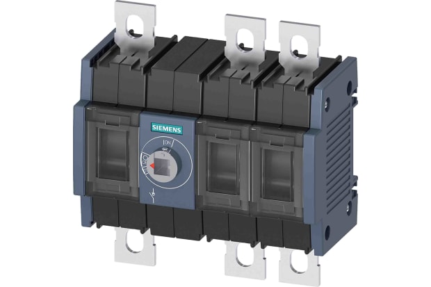
Siemens
With an extensive range of products available, shop Siemens isolators and switch disconnectors with RS.