- Published 12 Jun 2023
- Last Modified 29 Aug 2023
- 5 min
How to Wire a Relay
Knowing how to wire a specific relay type ensures the best function of your electrical device.

Reviewed by Karl Ralph, Technical Support Engineer (February 2023)
There are several relay options to choose from depending on function, and each of these relay options is wired differently. Our guide breaks down how to wire these different relays.
Wiring a Relay
Wiring an electrical relay can be a daunting experience when taking into consideration how many distinct types of relays exist. However, whilst varying in type, relays share the same feature of a relay switch diagram, known as a pin diagram, printed on the outside of the case. This diagram shows the number and locations of each pin so that you can ensure you’re attaching the relevant wire to the correct pin.
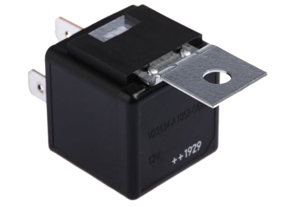
How to Wire a 4-Pin Car Relay
A 4-pin relay is a simple structured relay. The pin numbers on a 4-pin relay are 85, 86, 87 and 30. Pin 30 is the power supply for a relay, and pin 86 acts as the switch for that pin. 85 is the grounding pin and 87 is the pin connected to a device. When the power is switched on through pin 86, the circuit is closed, and the power source is connected through pin 30. This current then powers the device connected to 87.
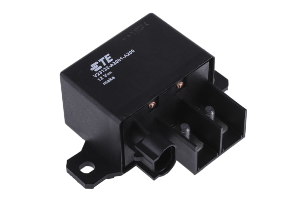
How to Wire a 12V Relay
A 12v relay is mostly found in vehicles to power devices and like a 4-pin relay, works on a four-point connection. Wires from either side of the coil need to connect through a switch, to both the positive and negative side of a power source, in this case, it would be the car’s power system. The relay’s moving part will also need to be connected to a power supply (this moving part is sometimes referred to as the common terminal or COM). Finally, the device is then connected to the normally open terminal. When power is on, this closes, and the device is powered.
How to Wire a Split Charge Relay
A split charge relay is a relay used to split power between two batteries. To wire in a split charge relay, the first step is to ensure the alternator and the batteries you are connecting share a negative charge. From there and using a wire connection, the positives on both batteries connect to the 87 and 30 pins on a split charge relay. The 86 pin will connect to the alternator, the connection point on an alternator being labelled F or D. Finally, the 85 pin connects to a negative side on either battery – whichever is most accessible from the relay.
Once all are connected, the alternator becomes the power source for your relay to work. When the alternator is working, the circuit will close in the relay and both batteries will charge.
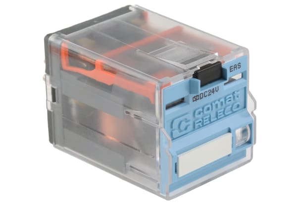
How to Wire a Relay Switch
A relay switch or a 5-pin is like a 4-pin relay, with the addition of pin number 87a. A 5-pin relay is wired the same as a 4-pin relay. The difference is that when a current isn’t sent through pins 85 and 86, rather than breaking a single circuit, the 5-pin relay will switch to the circuit connected to pin 87a.
How to Wire an 8-Pin Relay
On an 8-pin relay, the pins are numbered differently to account for more pins. 8 pin relays have two normally open circuits and two normally closed circuits, as opposed to one of each. From left to right at the top of a relay, the pins are numbered 6,5,4 and 3. From left to right at the bottom of a relay, the pins are numbered 7,8,1 and 2. Pins 8 and 1 are the pins that are responsible for bringing power into the circuit, whereas pins 5 and 4 are closed circuit pins, and 3 and 6 are open circuit pins. Pin 8 operates pins 5 and 6 and pin 1 operates pins 3 and 4. Finally, pins 2 and 7 are coil pins. When wiring, one of the coil pins must be neutral whilst the other is charged, to balance the circuit.

How to Wire a Safety Relay
Safety relays have a few more components to wire compared to a simple 4-pin relay. Like the 8-pin relay, the pins on a safety relay are numbered differently, the first of these being A1 and A2. These are the power wires that feed in current and ground power. S1, S12 and S22 are part of the input circuits that receive signals. These may be wired into a switch or a sensor and are a part of the circuit that advises about safety and creates a response in the reset circuit. The next pins (S33 and S34) are the reset part of the circuit that sends out a signal to create an action (for example, stopping machinery).
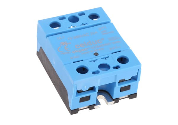
How to Wire a Contactor Relay
On a contactor relay, the required voltage will be present on the case, alongside the pin diagram. This will show the input voltage necessary for the relay to work.
The first pins to be connected on a contactor relay are the A1 and A2 pins. These are the power wires, A1 being the positive wire and A2 being the negative wire. The next set of pins is the L1, L2 and L3 pins. These pins are the input pins that receive a signal. Finally, pins T1, T2 and T3 are the reset pins and the pins that are affected by a power supply in the L1, L2, and L3 pins. The L1 pin is connected to the T1 pin, the L2 pin is connected to the T2 pin and the L3 pin is connected to the T3 pin.