- Published 30 Jan 2023
- Last Modified 19 Nov 2025
- 9 min
A Complete Guide to Contactors
Our guide provides everything you need to know about contactors, including how they work and how to use them.

Published October 2021
This introductory guide to contactors aims to provide clear and comprehensive answers to common questions about contactors. We will include a brief look at how electrical contactors work, how they are used and which types are sold online in the UK.
We will also cover some of the more popular types and brands of contactors available and identify how to choose the best for your needs.
What is a Contactor?
A contactor is an electrical device that is widely used for switching circuits on and off. As such, electrical contactors form a subcategory of electromagnetic switches known as relays.
A relay is an electrically operated switching device that uses an electromagnetic coil to open and close a set of contacts. This action results in a circuit powering either on or off (establishing or interrupting the circuit). A contactor is a specific type of relay, although there are some important differences between a relay and a contactor.
Contactors are principally designed for use in applications where a large amount of current needs to be switched. If you are looking for a concise electrical contactor definition, you could say something like the following:
A contactor is an electrically controlled switching device, designed for repeatedly opening and closing a circuit. Contactors tend to be used for higher current-carrying applications than standard relays, which do a similar job with low current switching.
What are Contactors Used for?
An electrical contactor is used in a wide range of situations where there is a need to switch power to a circuit repeatedly. Like relay switches, they are designed and built to perform this task over many thousands of cycles.
Contactors are mainly chosen for higher power applications than relays. This is because of their ability to allow low voltages and currents to switch, or power cycle, a far higher voltage/current circuit on and off.
Typically, a contactor will be used in situations where power loads need to be turned on and off frequently or rapidly. However, they can also be configured either to power on a circuit when activated (normally open, or NO contacts), or to shut down power to a circuit when activated (normally closed, or NC contacts).
The two classic applications for a contactor are as an electric motor starter - such as those that use auxiliary contacts and connectors for use in electrical vehicles - and in high-powered lighting control systems.
When a contactor is used as a magnetic starter for an electric motor, it will usually also provide a range of other safety features such as power-cutoff, short circuit protection, overload protection, and under-voltage protection.
Contactors being used to control high-power lighting installations will often be arranged in a latching configuration, to lower overall power consumption. This arrangement involves two electromagnetic coils working in tandem. One coil will close the circuit contacts when briefly energised and hold them closed magnetically. The second coil will open them again when powered. This sort of setup is especially common for the automation of large-scale office, commercial and industrial lighting setups. The principle is like how a latching relay works, although the latter is more often used in smaller circuits with reduced loads.
As contactors are intended specifically for these sorts of high voltage applications, they tend to be physically larger and more robust than standard relay switching devices. However, most electrical contactors are still designed to be easily portable and mountable and are generally considered highly suitable for use in the field.
Browse Contactors
Explore our Range of Quality Contactors
Sponsored
How Do Contactors Work?
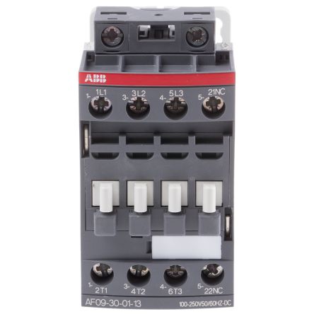
To better understand how a contactor works, it is helpful to know about the three core components of any electrical contactor device when assembled. These are normally the coil, the contacts, and the device enclosure.
- The coil, or electromagnet, is the key component of a contactor. Depending on how the device is set up, it will perform a specific action on the switch contacts (opening or closing them) when it receives power
- The contacts are the components of the device that carry power across the circuit being switched. There are various types of contacts found in most contactors, including springs and power contacts. Each type performs a specific function in transferring current and voltage
- The contactor enclosure is another important part of the device. This is the housing that surrounds the coil and contacts, helping to insulate the contactor’s key components. The enclosure protects users against accidentally touching any conductive parts of the switch, as well as offering robust protection against risks such as overheating, explosion, and environmental hazards like dirt and moisture ingress
The operating principle of an electrical contactor is straightforward. When the electromagnetic coil has a current passed through it, a magnetic field is created. This causes the armature within the contactor to move in a certain way regarding the electrical contacts.
Depending on how the specific device has been designed and the role it is intended for, this will normally be to either open or close the contacts.
- If the contactor is designed as normally open (NO), exciting the coil with voltage will push the contacts together, establish the circuit, and allow power to flow around the circuit. When the coil is de-energised, the contacts will be open, and the circuit will be off. This is how most contactors are designed
- A normally closed (NC) contactor works the opposite way. The circuit is complete (contacts closed) while the contactor is de-energised but interrupted (contacts open) whenever current is supplied to the electromagnet. This is a less common configuration for contactors, although it is a relatively common alternative setup for standard relay switches
Contactors can rapidly perform this switching task, over many thousands (or indeed millions) of cycles during their full working lives.
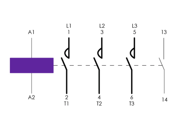
Contactor Wiring Diagram
A common example of a contactor wiring diagram might look something like this. This example diagram would be for a three-pole contactor with one N.O. base contact.
The Difference Between Contactors and Relays
Although we have already stated that contactors are used for higher power applications than relays, understanding the full technical differences between contactor vs relay is slightly more complex.
A more complete list of the differences between a contactor and a relay would include the following:
- Load capacity. Contactors are designed and built to handle much higher power switching applications than control relays. Relays are typically reserved for use with loads of around 5A-15A, and they are most often rated for 10A or less
- Contact standards. Contactors are almost always set up in a normally open (NO) configuration. This means that the circuit will only be established while the electromagnet in the contactor is receiving current. Relays are easy to find with both NO and NC contacts
- Protections and safety features. Contactors typically offer a much wider range of safety cut-offs and protections, reflecting the fact that they are designed for higher power applications. Indeed, a specific type of switch known as contactor overload relays is specifically designed for use in preventing machinery and power circuits from overheating
Elsewhere, common examples of standard contactor safety features include:
- Spring-loaded contacts, for interrupting an electrical circuit if the contactor is powered off
- Overload protection that kicks in if the circuit receives a current surge for a defined period
- Magnetic arc suppression, forcing any current arcs to travel a greater distance than the energy they carry can sustain
Due to contactors being intended for heavy-duty, higher power applications, they tend to be physically bigger and heavier than relays, and their switching speed is considerably slower. They are also more expensive than relays in most cases and consume more power due to their larger electromagnetic coils.
Contactors Selection Guide
Many different types of contactors are available to buy online in the UK and elsewhere, including single-phase contactors and three-phase contactors.
Choosing the best electrical contactor for a given application involves careful assessment of various important metrics, features, and specifications. Load requirements and power ratings (voltage and current) will always be among the most crucial considerations.
Types of Contactors
Magnetic Contactor
A magnetic switch contactor operates entirely via electromagnetism and therefore does not need any direct intervention to perform its role consistently. This makes it one of the more efficient and reliable designs since electromagnetic switching only requires a small amount of power. It also enables the full remote operation of the contactor. Almost all electrical contactors work on this basis today.
Switch Ratings and Coil Ratings (Contact Voltage and Current)
Contactor switch ratings are usually given as two separate metrics - maximum switching voltage and maximum switching current. The upper limits of both voltage and current that a design, brand, or model of a switch can handle must always be directly assessed in terms of the requirements for the circuit or motor where it is being used.
While a product may be listed as a 230V contactor, 240V contactor, or 1000V DC contactor, more detailed manufacturer specifications will usually make direct reference to the maximum coil voltage, contact current rating, contact voltage rating, and overall power rating of a device. They will also list the number of auxiliary contacts, terminal type, normal state configuration, and minimum and maximum operating temperatures. Contactors generate more heat than relays, and this must be factored in when choosing a suitable unit for installation.
Various electrical ratings for contactors will often be given as either resistive or inductive, depending on the intended use of the module. Resistive ratings are more common for contactors being used with heating elements or lighting control installations, whereas inductive load ratings tend to be more common for motors, transformers, and solenoids.
It is also worth bearing in mind that the contactor coil voltage (control circuit voltage) does not necessarily have to be the same as the load voltage being switched on and off. For example, the coil voltage could be 24VDC, but the motor being switched on and off could be 400VAC. Typical coil voltages available include 12, 24, 48, 110, 230, and 400V.
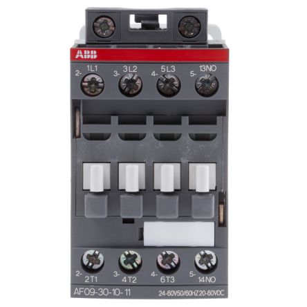
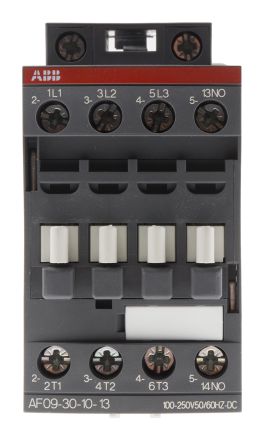
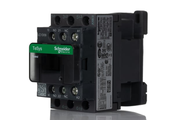
Contactor Brands
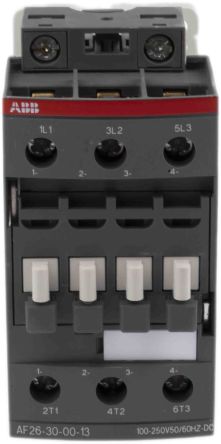
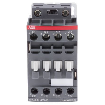
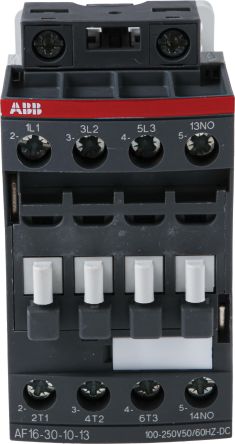
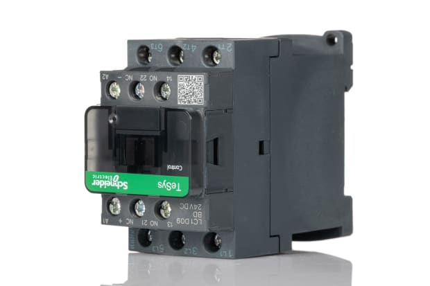
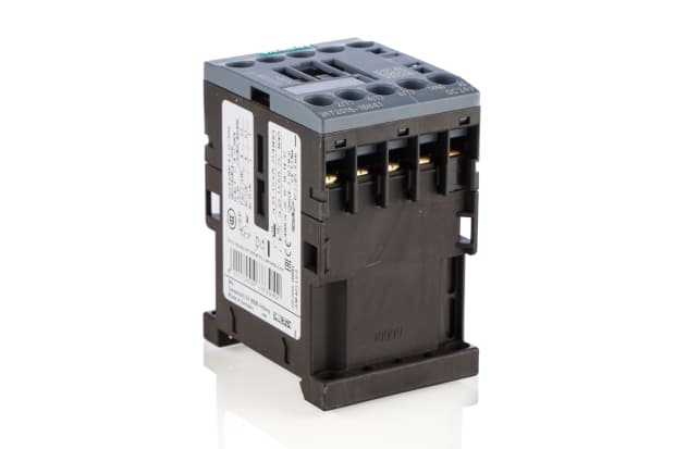
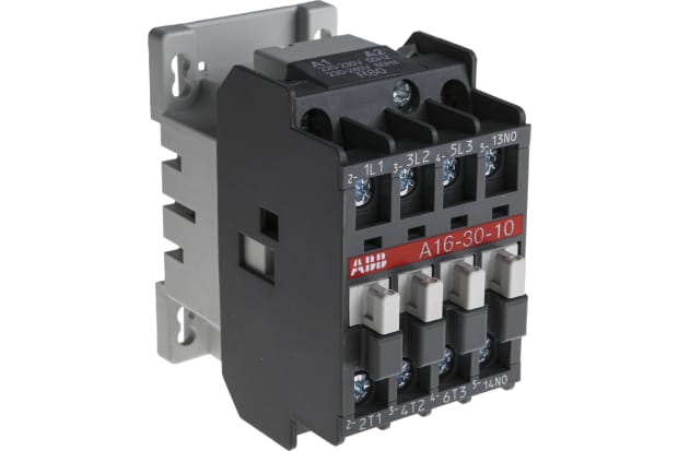
Many leading brands are renowned for manufacturing high quality, reliable electrical contactor switches. Among the most sought-after suppliers we work with to supply our extensive range of switches and contactor accessories are ABB, Allen Bradley, Eaton, Lovato, Schneider Electric, Siemens, TE Connectivity and WEG.
FAQs
What is the Most Common Reason for Contactor Failure?
There are several reasons why an electrical contactor could suffer a failure and need repair or replacement. The most common is contact welding or contact sticking, where the contacts of the device become stuck or fused in one position.
This is typically a result of excessive inrush currents, unstable control voltages, too low transition times between high peak currents, or simply due to normal wear and tear. The latter usually manifests as a gradual burning off of the alloys coating the contact terminals, causing the exposed copper underneath to weld together.
Another less common reason for a failing contactor is coil burn, most often caused by an excessive (or insufficient) voltage at either end of the electromagnetic coil. Dirt, dust, or moisture ingress into the air gap around the coil can also be a contributing factor.
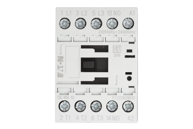
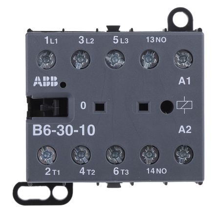
What Do A1 and A2 Mean on a Contactor?
A1 and A2 on a contactor typically refer to either end of the electromagnetic coil assembly. Most contactor manufacturers use A1 and A2 to designate the two terminals connecting electrical power to the contactor’s magnetic coil.
What are 13 and 14 on a Contactor?
13 and 14 on a contactor also refer to common manufacturer designations. In this case, they are used to label the terminals on the normally open contacts in the device.