- Published 19 Jun 2023
- Last Modified 25 Mar 2024
- 4 min
How TRIACs Work
TRIACs are a useful tool for people building AC circuits, but how do they work and what are the main TRIAC applications?

If you’ve ever used an electric fan, a dimmer switch or motor control, then you’re likely to have experienced the functionality of TRIACs. An electronic component that enables power switching or control within AC circuits, TRIACs’ unique mode of operation makes the solid-state device useful in a range of applications.
This article will explain exactly what TRIACs are, how they work and the ways they can be used in different AC circuits.
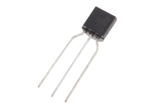
What are TRIACs?
TRIACs are silicon semiconductors that allow electrons to flow in both directions through three electrodes. It is made from four layers of silicon and has a PNPN function in the positive direction and an NPNP in the negative direction.
Specifically, TRIAC stands for ‘triode for alternating current’ and is often categorised as silicon-controlled rectifiers (SCRs) and thyristors. As such, it has the following key functions:
- Amplifying power from low to medium voltage (like other triodes)
- Allowing the bidirectional flow of AC currents (unlike SCRs and thyristors)
- Having two definitive states - on and off (as with other thyristors)
- Having conduction triggered by gate signals (similar to an SCR)
These characteristics make TRIACs useful as a switch or power control unit within an AC circuit.
TRIAC Symbol
The circuit symbol for TRIACs shows the three electrodes of the device, including both anodes and the gate. Although not all TRIAC devices will be constructed in exactly this way, they all have two SCRs that are linked antiparallel to each other via a cathode and anode. This means both terminals are labelled as anodes alongside the single gate that the SCRs in the device share.


TRIAC Principle of Operation and How They Work
Though the TRIACs principle of operation is often compared to two thyristors working in antiparallel, the construction of TRIAC devices (with a mix of N-type and P-type areas) means they can perform a switching function over both parts of the AC waveform. This means, unlike standard thyristors, TRIACs can work with the current flowing in either direction so only one device needs to be used for many applications.
It also means the device can perform conduction whether the polarity sent through the terminals is positive or negative. However, the sensitivity of the current required to trigger the device is highest when both terminals are the same type of polarity.
As such, the four triggering modes of operation are defined as follows:
- I+ Mode: Terminal 2 current is +ve, gate current is +ve
- I- Mode: Terminal 2 current is +ve, gate current is -ve
- III+ Mode: Terminal 2 current is -ve, gate current is +ve
- III- Mode: Terminal 2 current is -ve, gate current is -ve
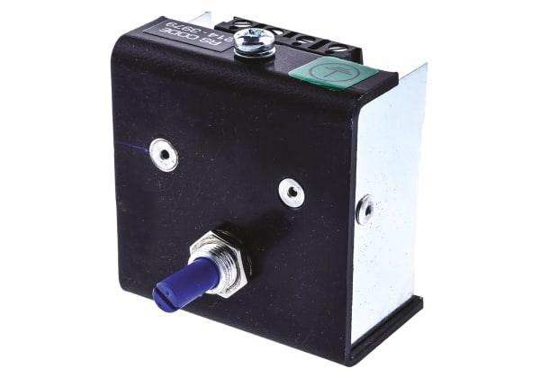
Uses of TRIACs
The functional requirement of a trigger from the gate end of the TRIAC means they’re an ideal device for creating switches in low-to-medium power AC circuits. This can include light, fan and motor controls or in temperature or liquid level control systems.
TRIAC as a Switch Circuit
For TRIAC circuits for AC switching to work, the following steps need to be completed:
- When the switch (SW1) is open in the below circuit, the TRIAC stays ‘OFF’ and no current passes through the lamp
- When the switch is closed, a trigger is sent into the TRIAC via the gate electrode and the TRIAC starts to conduct, switching to its ‘ON’ phase
- When only AC power is supplied to the TRIAC, the device will unlatch and relatch during each half-waveform cycle. This allows the current flowing through the lamp to be controlled
- The TRIAC will only switch off then the supplied current drops close to zero

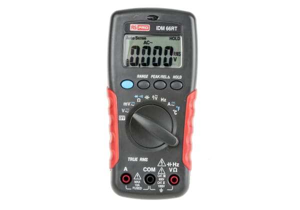
How to Test TRIACs
To test a TRIAC, you can use a digital multimeter (DMM). To make sure the device is working effectively, you need to follow these steps:
- Connect the positive and negative leads to each TRIAC terminal
- The reading on the DMM should be infinity
- You can also use a jumper wire to short-circuit the TRIAC gate, this should change the reading to 0
- Swapping the leads over on each terminal will change the DMM reading back to infinity
Getting these readings via these steps shows that the TRIAC is working as it should be in the circuit.