Vishay IRF9Z14 Type P-Channel MOSFET, 6.7 A, 60 V Enhancement, 3-Pin TO-220 IRF9Z14PBF
- RS Stock No.:
- 178-0838
- Mfr. Part No.:
- IRF9Z14PBF
- Brand:
- Vishay

Bulk discount available
View bulk pricing optionsSubtotal (1 tube of 50 units)*
£39.40
(exc. VAT)
£47.30
(inc. VAT)
FREE delivery for orders over £60.00
In Stock
- 700 unit(s) ready to ship
Need more? Click ‘Check delivery dates’ to find extra stock and lead times.
Units | Per unit | Per Tube* |
|---|---|---|
| 50 - 50 | £0.788 | £39.40 |
| 100 - 200 | £0.67 | £33.50 |
| 250 + | £0.591 | £29.55 |
*price indicative
- RS Stock No.:
- 178-0838
- Mfr. Part No.:
- IRF9Z14PBF
- Brand:
- Vishay
Specifications
Technical Reference
Legislation and Compliance
Product Details
Find similar products by selecting one or more attributes.
Select all | Attribute | Value |
|---|---|---|
| Brand | Vishay | |
| Channel Type | Type P | |
| Product Type | MOSFET | |
| Maximum Continuous Drain Current Id | 6.7A | |
| Maximum Drain Source Voltage Vds | 60V | |
| Series | IRF9Z14 | |
| Package Type | TO-220 | |
| Mount Type | Through Hole | |
| Pin Count | 3 | |
| Maximum Drain Source Resistance Rds | 500mΩ | |
| Channel Mode | Enhancement | |
| Maximum Gate Source Voltage Vgs | 20V | |
| Minimum Operating Temperature | -55°C | |
| Forward Voltage Vf | -5.5V | |
| Typical Gate Charge Qg @ Vgs | 12nC | |
| Maximum Power Dissipation Pd | 43W | |
| Maximum Operating Temperature | 175°C | |
| Width | 4.7mm | |
| Height | 9.01mm | |
| Length | 10.41mm | |
| Standards/Approvals | No | |
| Automotive Standard | No | |
| Select all | ||
|---|---|---|
Brand Vishay | ||
Channel Type Type P | ||
Product Type MOSFET | ||
Maximum Continuous Drain Current Id 6.7A | ||
Maximum Drain Source Voltage Vds 60V | ||
Series IRF9Z14 | ||
Package Type TO-220 | ||
Mount Type Through Hole | ||
Pin Count 3 | ||
Maximum Drain Source Resistance Rds 500mΩ | ||
Channel Mode Enhancement | ||
Maximum Gate Source Voltage Vgs 20V | ||
Minimum Operating Temperature -55°C | ||
Forward Voltage Vf -5.5V | ||
Typical Gate Charge Qg @ Vgs 12nC | ||
Maximum Power Dissipation Pd 43W | ||
Maximum Operating Temperature 175°C | ||
Width 4.7mm | ||
Height 9.01mm | ||
Length 10.41mm | ||
Standards/Approvals No | ||
Automotive Standard No | ||
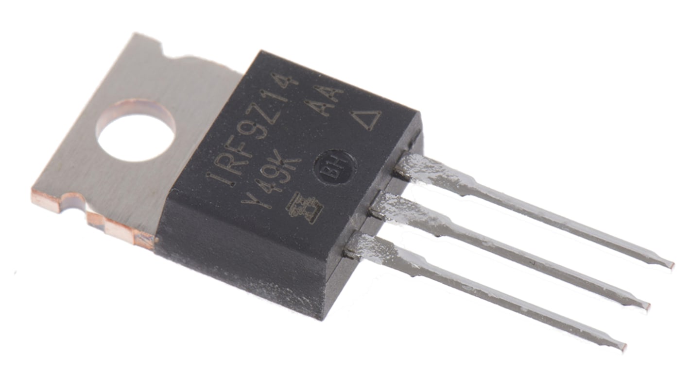
Vishay IRF9Z14 Series Power MOSFET, -60V Maximum Drain Source Voltage, -6.7A Maximum Continuous Drain Current - IRF9Z14PBF
This power MOSFET is a P‑channel enhancement device intended for switching and control in electronic systems. It is supplied in a through‑hole TO‑220AB package and is suited to applications that require a discrete transistor capable of handling moderate currents and voltages while operating across a wide temperature range.
Features and Benefits:
• -60V drain‑source rating enables high‑voltage switching
• -6.7A continuous drain current supports medium‑power loads
• 500mΩ Rds(on) reduces conduction losses under load
• 12nC typical gate charge allows reasonably fast switching
• 43W power dissipation manages thermal load in controlled environments
• 20V maximum gate‑source withstand simplifies gate‑drive design
Applications
• Suitable for DC motor high‑side switching in automation systems
• Ideal for power control in industrial electronics modules
• Used with thermal management assemblies in mechanical drives
• Can be used for load switching in electrical distribution panels
• Ideal for power control in industrial electronics modules
• Used with thermal management assemblies in mechanical drives
• Can be used for load switching in electrical distribution panels
What temperature extremes can the device tolerate in operation?
It is rated to operate between -55°C and 175°C, allowing use in environments with wide thermal variation.
How many electrical connections does the package provide for assembly?
The through‑hole TO‑220AB format presents three pins for straightforward PCB or chassis mounting.
What gate‑drive considerations should be observed for switching?
The gate‑source maximum is 20V and the typical gate charge is 12nC, so drive circuits should limit Vgs and provide sufficient current to charge the gate at the intended switching speed.
Are there any environmental or regulatory material standards noted for the part?
The device meets RoHS requirements for restricted substances in electronic components.
Related links
- Vishay IRF9Z14 Type P-Channel MOSFET 60 V Enhancement, 3-Pin TO-220
- onsemi PowerTrench Type P-Channel MOSFET 12 V Enhancement, 3-Pin TO-252
- onsemi PowerTrench Type P-Channel MOSFET 12 V Enhancement, 3-Pin TO-252 FDD306P
- onsemi PowerTrench Type P-Channel MOSFET 40 V Enhancement, 3-Pin TO-252
- onsemi PowerTrench Type P-Channel MOSFET 40 V Enhancement, 3-Pin TO-252 FDD4243
- Vishay IRFI Type P-Channel MOSFET 60 V Enhancement, 3-Pin TO-220
- Vishay IRF9Z34 Type P-Channel Power MOSFET 60 V Enhancement, 3-Pin TO-220 IRF9Z34PBF
- Vishay IRFI Type P-Channel MOSFET 60 V Enhancement, 3-Pin TO-220 IRFI9Z24GPBF