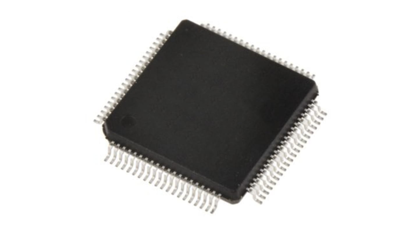
STMicroelectronics STM32G491MET6, 32 bit ARM Cortex M4, STM32G491 Microcontroller, 48 MHz, 512kB FLASH, 100-Pin BGA
- RS Stock No.:
- 215-0845
- Mfr. Part No.:
- STM32G491MET6
- Brand:
- STMicroelectronics

Bulk discount available
View bulk pricing optionsSubtotal (1 pack of 2 units)*
£12.16
(exc. VAT)
£14.60
(inc. VAT)
FREE delivery for orders over £60.00
Temporarily out of stock
- Shipping from 18 December 2026
Need more? Click ‘Check delivery dates’ to find extra stock and lead times.
Units | Per unit | Per Pack* |
|---|---|---|
| 2 - 18 | £6.08 | £12.16 |
| 20 - 48 | £5.93 | £11.86 |
| 50 + | £5.775 | £11.55 |
*price indicative
- RS Stock No.:
- 215-0845
- Mfr. Part No.:
- STM32G491MET6
- Brand:
- STMicroelectronics
Specifications
Technical Reference
Legislation and Compliance
Product Details
Find similar products by selecting one or more attributes.
Select all | Attribute | Value |
|---|---|---|
| Brand | STMicroelectronics | |
| Series | STM32G491 | |
| Product Type | Microcontroller | |
| Package Type | BGA | |
| Mount Type | Surface | |
| Pin Count | 100 | |
| Device Core | ARM Cortex M4 | |
| Data Bus Width | 32bit | |
| Program Memory Size | 512kB | |
| Maximum Clock Frequency | 48MHz | |
| RAM Size | 112kB | |
| Maximum Supply Voltage | 3.6V | |
| DACs | 4 x 12 Bit | |
| Minimum Operating Temperature | -40°C | |
| Analogue Comparators | 4 | |
| Maximum Operating Temperature | 85°C | |
| Length | 14mm | |
| Standards/Approvals | No | |
| Width | 14mm | |
| Height | 1.6mm | |
| Minimum Supply Voltage | 1.71V | |
| Program Memory Type | FLASH | |
| ADCs | 1 x 3 Bit | |
| Number of Timers | 15 | |
| Automotive Standard | No | |
| Instruction Set Architecture | RISC | |
| Select all | ||
|---|---|---|
Brand STMicroelectronics | ||
Series STM32G491 | ||
Product Type Microcontroller | ||
Package Type BGA | ||
Mount Type Surface | ||
Pin Count 100 | ||
Device Core ARM Cortex M4 | ||
Data Bus Width 32bit | ||
Program Memory Size 512kB | ||
Maximum Clock Frequency 48MHz | ||
RAM Size 112kB | ||
Maximum Supply Voltage 3.6V | ||
DACs 4 x 12 Bit | ||
Minimum Operating Temperature -40°C | ||
Analogue Comparators 4 | ||
Maximum Operating Temperature 85°C | ||
Length 14mm | ||
Standards/Approvals No | ||
Width 14mm | ||
Height 1.6mm | ||
Minimum Supply Voltage 1.71V | ||
Program Memory Type FLASH | ||
ADCs 1 x 3 Bit | ||
Number of Timers 15 | ||
Automotive Standard No | ||
Instruction Set Architecture RISC | ||
Mainstream Arm Cortex-M4 MCU 170 MHz with 512 Kbytes of Flash memory, Math Accelerator, Medium Analog level integration
The STMicroelectronics STM32G491xC/xE devices are based on the high-performance Arm® Cortex®-M4 32-bit RISC core. They operate at a frequency of up to 170 MHz.;The Cortex-M4 core features a single-precision floating-point unit (FPU), which supports all the Arm single-precision data-processing instructions and all the data types. It also implements a full set of DSP (digital signal processing) instructions and a memory protection unit (MPU) which enhances the application’s security.;These devices embed high-speed memories (512 Kbytes of Flash memory, and 112 Kbytes of SRAM), a Quad SPI Flash memory interface, an extensive range of enhanced I/Os and peripherals connected to two APB buses, two AHB buses and a 32-bit multi-AHB bus matrix.;The devices also embed several protection mechanisms for embedded Flash memory and SRAM: readout protection, write protection, securable memory area and proprietary code readout protection.;The devices embed peripherals allowing mathematical/arithmetic function acceleration (CORDIC for trigonometric functions and FMAC unit for filter functions).;They offer three fast 12-bit ADCs (5 Msps), four comparators, four operational amplifiers, four DAC channels (2 external and 2 internal), an internal voltage reference buffer, a low-power RTC, one general-purpose 32-bit timers, three 16-bit PWM timers dedicated to motor control, seven general-purpose 16-bit timers, and one 16-bit low-power timer.
They also feature standard and advanced communication interfaces such as:;Three I2Cs ;Three SPIs multiplexed with two half duplex I2Ss ;Three USARTs, two UARTs and one low-power UART. ;Two FDCANs ;One SAI ;USB device ;UCPD
The devices operate in the -40 to +85 °C (+105 °C junction) and -40 to +125 °C (+130 °C junction) temperature ranges from a 1.71 to 3.6 V power supply. A comprehensive set of power-saving modes allows the design of low-power applications.;Some independent power supplies are supported including an analog independent supply input for ADC, DAC, OPAMPs and comparators. A VBAT input allows backup of the RTC and the registers.;The STM32G491xC/xE family offers 9 packages from 32-pin to 100-pin.
Key Features
Core: Arm® 32-bit Cortex®-M4 CPU with FPU, Adaptive real-time accelerator (ART Accelerator) allowing 0-wait-state execution from Flash memory, frequency up to 170 MHz with 213 DMIPS, MPU, DSP instructions
Operating conditions:
- VDD, VDDA voltage range: 1.71 V to 3.6 V
Mathematical hardware accelerators
- CORDIC for trigonometric functions acceleration
- FMAC: filter mathematical accelerator
Memories
- 512 Kbytes of Flash memory with ECC support, proprietary code readout protection (PCROP), securable memory area, 1 Kbyte OTP
- 96 Kbytes of SRAM, with hardware parity check implemented on the first 32 Kbytes
- Routine booster: 16 Kbytes of SRAM on instruction and data bus, with hardware parity check (CCM SRAM)
- Quad-SPI memory interface
Reset and supply management
- Power-on/power-down reset (POR/PDR/BOR)
- Programmable voltage detector (PVD)
- Low-power modes: sleep, stop, standby and shutdown
- VBAT supply for RTC and backup registers
Clock management
- 4 to 48 MHz crystal oscillator
- 32 kHz oscillator with calibration
- Internal 16 MHz RC with PLL option (± 1%)
- Internal 32 kHz RC oscillator (± 5%)
Up to 86 fast I/Os
- All mappable on external interrupt vectors
- Several I/Os with 5 V tolerant capability
Interconnect matrix
16-channel DMA controller
3 x ADCs 0.25 µs (up to 36 channels). Resolution up to 16-bit with hardware oversampling, 0 to 3.6 V conversion range
4 x 12-bit DAC channels
- 2 x buffered external channels 1 MSPS
- 2 x unbuffered internal channels 15 MSPS
4 x ultra-fast rail-to-rail analog comparators
4 x operational amplifiers that can be used in PGA mode, all terminals accessible
Internal voltage reference
Related links
- STMicroelectronics STM32G491 Microcontroller 512kB FLASH, 100-Pin BGA
- STMicroelectronics STM32G491CEU6 STM32G491 Microcontroller 512kB FLASH, 100-Pin BGA
- STMicroelectronics STM32G491RET6 STM32G491 Microcontroller 512kB FLASH, 100-Pin BGA
- STMicroelectronics STM32G491REI6 STM32G491 Microcontroller 512kB FLASH, 100-Pin BGA
- STMicroelectronics STM32G491VET6 STM32G491 Microcontroller 512kB FLASH, 100-Pin BGA
- STMicroelectronics STM32G491KEU6 STM32G491 Microcontroller 512kB FLASH, 100-Pin BGA
- STMicroelectronics STM32G491CET6 STM32G491 Microcontroller 512kB FLASH, 48-Pin LQFP
- STMicroelectronics STM32G491 Microcontroller 512kB FLASH, 48-Pin LQFP