- Published 16 Jun 2023
- Last Modified 29 Aug 2023
- 6 min
What is UART?
Find out all you need to know about UART microcontrollers and protocols, how they work and what you can use them for.
UART stands for universal asynchronous receiver transmitter. As the name suggests, this chip is placed in a physical circuit board to enable a device to receive and transmit data. Also known as a device-to-device communication protocol, UARTs were one of the first technologies to enable secure and reliable data transmission.
Though this technology has advanced since the invention of UART chips, with many modern devices using alternative protocols, they are still a low-cost option for those looking to add an easy-to-use serial protocol to their circuit board.
This guide will outline the history of UART development, explain how they work and how they can be used.
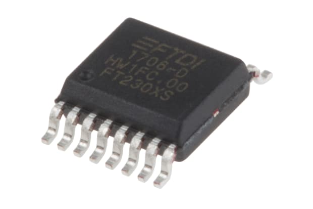
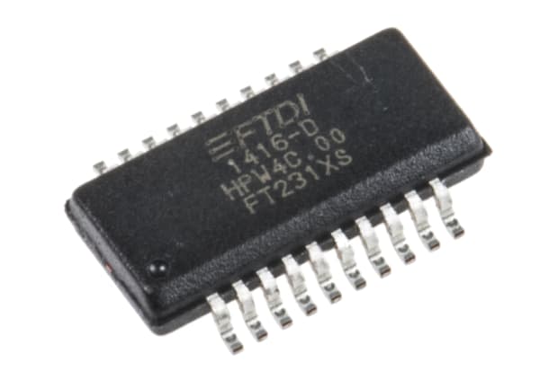
What is a UART Chip?
A UART chip is a physical component that can be put into a circuit board to enable the transfer of data. Two UART chips are installed in a circuit board so data can be transmitted and received between data buses.
UART chips do this by breaking down information into bits and transferring them across one at a time. This transmission can be started or stopped at any time, hence UART includes the term asynchronous.
What is UART Protocol?
A UART protocol is the way data is transmitted between UART chips. UART protocol is asynchronous, meaning that it does not depend on a clock to synchronise and control the transmission of data between two devices.
Instead, transmitting UART chips add start and stop bits to data packets they receive from data buses. These bits indicate to the receiving UART chip when the data transfer has begun and when it has ended. To suit their needs, users can connect UARTs within the circuit board to control the speed and frequency of data transmission, otherwise known as the baud rate.
The History of UART
The first UART chip was created by an engineer called Chester Gordon Bell and was the size of a whole circuit board. This circuit board was designed for use in computer programmable data processing.
In the 1990s, UART technology was refined to make data transfer speedier and more secure with the use of on-chip buffers. In the 2000s, UARTs were adapted alongside the progression of serial bus technology. Again, this was an attempt to speed up the accurate transmission of data.
This led to the development of technologies such as USB to UART connectors, or bridges. These take data from the device connected via USB and transmit it via UART. They’re widely used as an alternative to the RS232 port because USB to UART connectors are directly interfaced with microcontrollers, making them more adaptable and versatile.
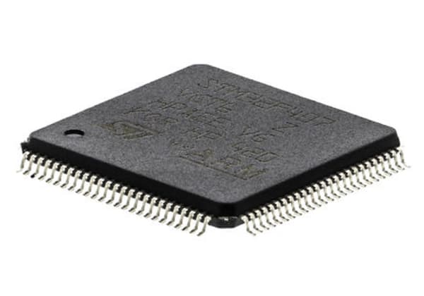
Other modern-day UART microcontrollers include:
- Raspberry Pi UART. This type of UART comes in two models, the PL011 and the Mini UART. The Mini UART is primarily used with the Linux console, while the PL011 can also be used for Bluetooth applications. The main difference between the two is the data transfer stability, with the Mini UART using frequencies from the core GPU, which can cause a loss or damage to data. The PL011 is a more advanced and stable technology, so is more secure when transferring data
- Arduino UART. Arduino is a microcontroller or programmable circuit board that uses UART data transmission. Although Arduino UART is slow at transmitting data compared to other technologies, it is straightforward to use and lots of tutorials and resources can be found online, making it a popular choice for DIY users
How Does UART Work?
UART works by sending data signals (or packets) between two parallel chips which are connected to each other by two wires. These chips are referred to as transferring and receiving UARTs depending on whether they’re sending or collecting the data.
Each of these chips is also connected to a data bus within a device that transmits or receives data. As such, the UART protocol works as follows:
- To start, the transmitting UART chip receives signals from the data bus. This data bus sends this signal to the chip in a parallel form, meaning the data in the chip will mirror that sent by the bus
- Once the data is received, the transmitting UART chip adds a start bit, parity bit and stop bit to the received data (known as the data frame) in preparation for transmission. These bits are expressed as either a 1 or a 0. The start and stop bits mark the beginning and end of data transmission, making them key to the asynchronous nature of UART data transmission
- This creates what is known as a data packet, which includes:
- The start bit causes a drop in voltage to kickstart the data transmission process
- The data frame is usually comprised of five to eight data bits and is the actual content being transferred i.e. it’s the data that will be used by the receiving data bus
- The parity bit acts as a quality check system for the data. The receiving UART will read this to determine if all the data has been transferred. If the parity bit reads 1 the number of data bits expressed as 1 in the frame should be even. If it reads as 0 the number should be odd. If the data and parity bit doesn’t match, then some data has been lost during transmission
- The stop bit causes the voltage to rise and marks the end of data transmission
- Once prepared, the entire data packet is sent to the receiving UART chip at the set baud rate, beginning with the start bit and finishing with the stop bit
- The receiving UART removes the start, stop and parity bit, leaving the data frame intact
- This data frame is sent out in parallel and bit by bit to the receiving data bus, completing the transmission
How to Use UART
To use UART protocols, two UART chips need to be connected together via two wires. Each of these chips also needs to be linked to individual data buses within the circuit board. To use UART successfully, it’s also important to keep the following points in mind:
- To ensure that data isn’t damaged or lost, the sending and receiving frequencies (i.e. the baud rate) in each UART chip should share at least 90% similarity. This will ensure the data transmitted by the UART is stable and remains secure
- The data frame within UART packets is restricted to up to nine bits, which may mean it’s not suitable for users looking to do more complex communications
- Though users can adapt the parallel nature of UART protocol to enable data packet structures to be changed, these systems can’t support multiple master-slave communication models
Due to the simplicity of its setup, there are many applications for UART, including GPS units, wireless connection and internal computer processing. There’s also plenty of help and advice available for UART protocols, making them a popular choice for creating DIY circuit boards that transmit data.
How to Test UART
The best method of testing is to use a script to assess the function of a UART. These can be readily found online and will run a test mode through a UART and show whether the data has been transferred successfully.
There are also test programmes that can be bought to analyse the efficiency and stability of data transmission in a UART. They run a simulation to test all areas of a UART and will flag any errors in its function.
Further Reading
Everything You Need to Know About Microcontrollers
This comprehensive guide examines what microcontrollers are and what they are used for, as well as the different types that are available on the market.

What are Raspberry Pi and Arduino?
What are development tools? Find out everything you need to know, including comparisons of popular products like Raspberry Pi and Arduino.
An Introductory Guide to Semiconductors
This guide introduces semiconductors, from the definition of a semiconductor to the usage of semiconductors in transistors, diodes, and LEDs.