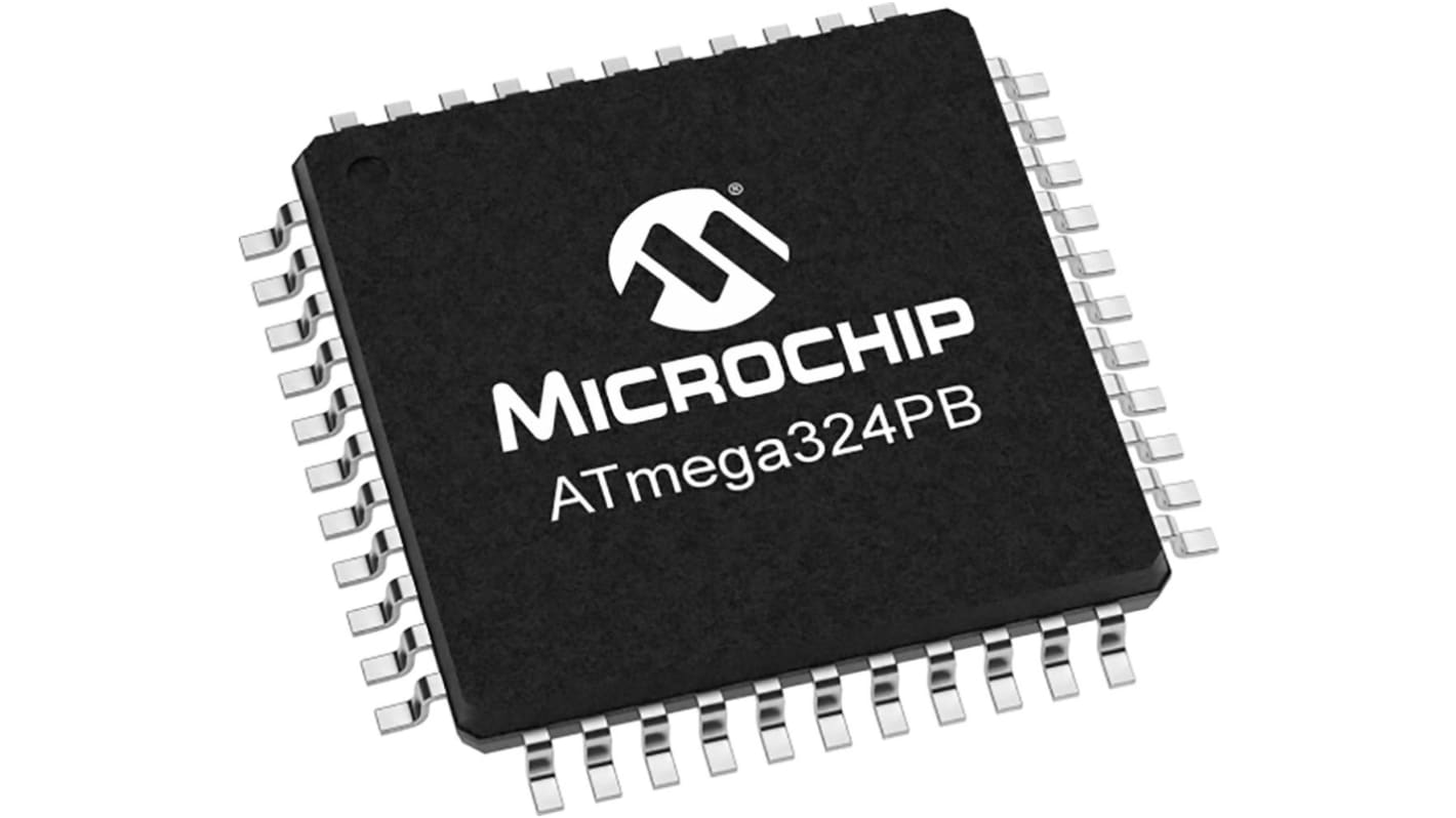
Microchip, 8 bit AVR, ATMEGA324PB Microcontroller, 20 MHz, 8kB FLASH, 44-Pin 44A
- RS Stock No.:
- 199-5366
- Mfr. Part No.:
- ATMEGA324PB-AN
- Brand:
- Microchip

Subtotal (1 tray of 160 units)*
£214.88
(exc. VAT)
£257.92
(inc. VAT)
FREE delivery for orders over £60.00
In Stock
- 320 unit(s) ready to ship
Need more? Click ‘Check delivery dates’ to find extra stock and lead times.
Units | Per unit | Per Tray* |
|---|---|---|
| 160 + | £1.343 | £214.88 |
*price indicative
- RS Stock No.:
- 199-5366
- Mfr. Part No.:
- ATMEGA324PB-AN
- Brand:
- Microchip
Specifications
Technical Reference
Legislation and Compliance
Product Details
Find similar products by selecting one or more attributes.
Select all | Attribute | Value |
|---|---|---|
| Brand | Microchip | |
| Product Type | Microcontroller | |
| Series | ATMEGA324PB | |
| Package Type | 44A | |
| Mount Type | Surface | |
| Pin Count | 44 | |
| Device Core | AVR | |
| Data Bus Width | 8bit | |
| Program Memory Size | 8kB | |
| Maximum Clock Frequency | 20MHz | |
| RAM Size | 2kB | |
| Maximum Supply Voltage | 5.5V | |
| Number of Programmable I/Os | 39 | |
| Minimum Operating Temperature | -40°C | |
| Analogue Comparators | 1 | |
| Maximum Operating Temperature | 85°C | |
| Standards/Approvals | RoHS | |
| Width | 7.1mm | |
| Length | 10.1mm | |
| Height | 1.05mm | |
| Minimum Supply Voltage | 1.8V | |
| Number of Timers | 5 | |
| Program Memory Type | FLASH | |
| Instruction Set Architecture | RISC | |
| Automotive Standard | AEC-Q100 | |
| ADCs | 8 x 10 Bit | |
| Select all | ||
|---|---|---|
Brand Microchip | ||
Product Type Microcontroller | ||
Series ATMEGA324PB | ||
Package Type 44A | ||
Mount Type Surface | ||
Pin Count 44 | ||
Device Core AVR | ||
Data Bus Width 8bit | ||
Program Memory Size 8kB | ||
Maximum Clock Frequency 20MHz | ||
RAM Size 2kB | ||
Maximum Supply Voltage 5.5V | ||
Number of Programmable I/Os 39 | ||
Minimum Operating Temperature -40°C | ||
Analogue Comparators 1 | ||
Maximum Operating Temperature 85°C | ||
Standards/Approvals RoHS | ||
Width 7.1mm | ||
Length 10.1mm | ||
Height 1.05mm | ||
Minimum Supply Voltage 1.8V | ||
Number of Timers 5 | ||
Program Memory Type FLASH | ||
Instruction Set Architecture RISC | ||
Automotive Standard AEC-Q100 | ||
ADCs 8 x 10 Bit | ||
The Microchip ATmega324PB CMOS 8-bit microcontroller is based on the AVR enhanced RISC architecture. It operates on 1.8V to 5.5V voltage supply. The AVR core combines a rich instruction set with 32 general purpose working registers. It features 32K bytes of In-System Programmable Flash with Read-While-Write capabilities, 1Kbytes EEPROM, 2Kbytes SRAM, 39 general purpose I/O lines, 32 general purpose working registers, five flexible Timer/Counters with compare modes, internal and external interrupts, three serial programmable USART, two byte-oriented 2-wire Serial Interface (I2C), two SPI serial port, a 8-channel 10-bit ADC with optional differential input stage with programmable gain, a programmable Watchdog Timer with internal Oscillator, IEEE std. 1149.1 compliant JTAG test interface, also used for accessing the On-chip debug system and programming, clock failure detection mechanism and six software selectable power saving modes. The Idle mode stops the CPU while allowing the SRAM, Timer/Counters, USART, 2-wire Serial Interface, SPI port, and interrupt system to continue functioning. PTC with enabling up to 32 self-cap and 256 mutual-cap sensors. The Power-down mode saves the register contents but freezes the Oscillator, disabling all other chip functions until the next interrupt or hardware reset.
Up to 20 MIPS throughput at 20MHz
Programming lock for software security
Boundary-scan capabilities according to the JTAG Standard
Extensive on-chip debug support
Programming of flash, EEPROM, fuses, and lock bits through the JTAG Interface
Two 8-bit Timer/Counters with separate prescaler and compare mode
Real time counter with separate oscillator
Two Master/Slave SPI serial interfaces
Programmable watchdog timer with separate on-chip oscillator
Power-on Reset and Programmable Brown-out Detection
Internal 8 MHz Calibrated Oscillator
External and Internal Interrupt Sources
Clock Failure detection mechanism and switch to internal 8 MHz RC oscillator in case of Failure
Individual serial number to represent a unique ID
Related links
- Microchip ATMEGA324PB-AN ATMEGA324PB Microcontroller 8kB FLASH, 44-Pin 44A
- Microchip ATMEGA644PV Microcontroller 8kB FLASH, 44-Pin 44A
- Microchip ATMEGA644PV-10AU ATMEGA644PV Microcontroller 8kB FLASH, 44-Pin 44A
- Microchip AT89S51 Microcontroller 8kB FLASH, 44-Pin 44A
- Microchip AT89LP52 Microcontroller 8kB FLASH, 44-Pin 44A
- Microchip ATMEGA324PB Microcontroller 32kB FLASH, 44-Pin TQFP
- Microchip AT89LP52-20AU AT89LP52 Microcontroller 8kB FLASH, 44-Pin 44A
- Microchip AT89S51-24AU AT89S51 Microcontroller 8kB FLASH, 44-Pin 44A