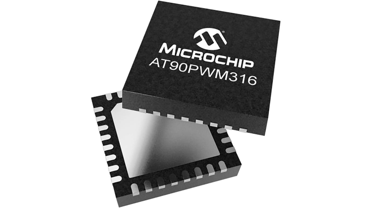
Microchip AT90PWM316-16MU, 8 bit AVR, AT90PWM316 Microcontroller, 20 MHz, 8kB FLASH, 32-Pin QFN
- RS Stock No.:
- 199-5355
- Mfr. Part No.:
- AT90PWM316-16MU
- Brand:
- Microchip

Subtotal (1 pack of 5 units)*
£12.95
(exc. VAT)
£15.55
(inc. VAT)
FREE delivery for orders over £50.00
- Shipping from 01 April 2026
Units | Per unit | Per Pack* |
|---|---|---|
| 5 - 20 | £2.59 | £12.95 |
| 25 - 95 | £2.512 | £12.56 |
| 100 + | £2.422 | £12.11 |
*price indicative
- RS Stock No.:
- 199-5355
- Mfr. Part No.:
- AT90PWM316-16MU
- Brand:
- Microchip
Select all | Attribute | Value |
|---|---|---|
| Brand | Microchip | |
| Series | AT90PWM316 | |
| Product Type | Microcontroller | |
| Package Type | QFN | |
| Mount Type | Surface | |
| Pin Count | 32 | |
| Device Core | AVR | |
| Data Bus Width | 8bit | |
| Interface Type | SPI, UART | |
| Program Memory Size | 8kB | |
| Maximum Clock Frequency | 20MHz | |
| RAM Size | 1kB | |
| Maximum Supply Voltage | 5.5V | |
| Number of Programmable I/Os | 27 | |
| Analogue Comparators | 2 | |
| Minimum Operating Temperature | -40°C | |
| DACs | 10 Bit | |
| Maximum Operating Temperature | 85°C | |
| Width | 7 mm | |
| Height | 1mm | |
| Standards/Approvals | RoHS | |
| Length | 7mm | |
| Minimum Supply Voltage | 2.7V | |
| Number of Timers | 2 | |
| Program Memory Type | FLASH | |
| ADCs | 11 x 10 Bit | |
| Instruction Set Architecture | RISC | |
| Automotive Standard | No | |
| Select all | ||
|---|---|---|
Brand Microchip | ||
Series AT90PWM316 | ||
Product Type Microcontroller | ||
Package Type QFN | ||
Mount Type Surface | ||
Pin Count 32 | ||
Device Core AVR | ||
Data Bus Width 8bit | ||
Interface Type SPI, UART | ||
Program Memory Size 8kB | ||
Maximum Clock Frequency 20MHz | ||
RAM Size 1kB | ||
Maximum Supply Voltage 5.5V | ||
Number of Programmable I/Os 27 | ||
Analogue Comparators 2 | ||
Minimum Operating Temperature -40°C | ||
DACs 10 Bit | ||
Maximum Operating Temperature 85°C | ||
Width 7 mm | ||
Height 1mm | ||
Standards/Approvals RoHS | ||
Length 7mm | ||
Minimum Supply Voltage 2.7V | ||
Number of Timers 2 | ||
Program Memory Type FLASH | ||
ADCs 11 x 10 Bit | ||
Instruction Set Architecture RISC | ||
Automotive Standard No | ||
Related links
- Microchip AT90PWM316 Microcontroller 8kB FLASH, 32-Pin QFN
- Microchip AT90PWM3B-16MU AT90PWM3B Microcontroller 8kB FLASH, 32-Pin QFN
- Microchip AT90PWM3B Microcontroller 8kB FLASH, 32-Pin QFN
- Microchip ATMEGA88PA-MU ATMEGA88PA Microcontroller 8kB FLASH, 32-Pin QFN
- Microchip ATMEGA88PA-AUR ATMEGA88PA Microcontroller 8kB FLASH, 32-Pin TQFP
- Microchip ATMEGA808-AF MegaAVR 0 Microcontroller 8kB FLASH, 32-Pin TQFP
- Microchip ATMEGA88-20MU ATMEGA88 Microcontroller 8kB FLASH, 32-Pin 32M1-A
- Microchip ATTINY861A-MU ATTINY861A Microcontroller 8kB FLASH, 32-Pin MLF
