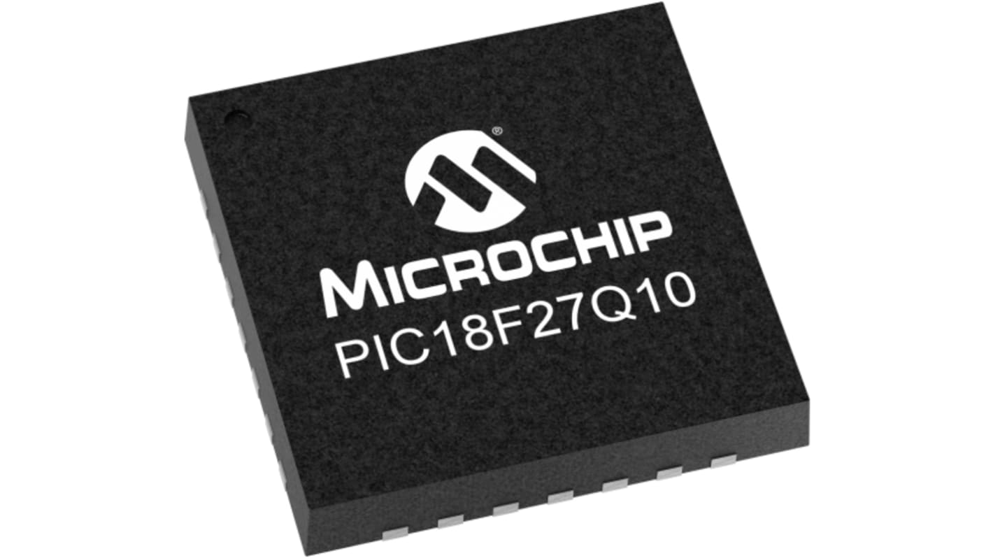
Microchip, 8bit PIC, PIC18F Microcontroller, 64MHz, 128 kB Flash, 28-Pin VQFN
- RS Stock No.:
- 193-6505
- Mfr. Part No.:
- PIC18F27Q10-I/STX
- Brand:
- Microchip

Subtotal (1 tube of 91 units)*
£67.431
(exc. VAT)
£80.899
(inc. VAT)
FREE delivery for orders over £50.00
- Shipping from 27 March 2026
Units | Per unit | Per Tube* |
|---|---|---|
| 91 + | £0.741 | £67.43 |
*price indicative
- RS Stock No.:
- 193-6505
- Mfr. Part No.:
- PIC18F27Q10-I/STX
- Brand:
- Microchip
Select all | Attribute | Value |
|---|---|---|
| Brand | Microchip | |
| Family Name | PIC18F | |
| Package Type | VQFN | |
| Mounting Type | Surface Mount | |
| Pin Count | 28 | |
| Device Core | PIC | |
| Data Bus Width | 8bit | |
| Program Memory Size | 128 kB | |
| Maximum Frequency | 64MHz | |
| RAM Size | 3.615 MB | |
| USB Channels | 0 | |
| Number of PWM Units | 1 x 10 bit | |
| Number of SPI Channels | 2 | |
| Typical Operating Supply Voltage | 1.8 → 5.5 V | |
| Number of USART Channels | 2 | |
| Number of CAN Channels | 0 | |
| Number of UART Channels | 2 | |
| Number of I2C Channels | 2 | |
| Width | 4mm | |
| Instruction Set Architecture | Harvard | |
| Maximum Number of Ethernet Channels | 0 | |
| Dimensions | 4 x 4 x 0.95mm | |
| ADCs | 24 x 10 bit | |
| Number of ADC Units | 1 | |
| Pulse Width Modulation | 1 (2 x 10 bit) | |
| Maximum Operating Temperature | +85 °C | |
| Length | 4mm | |
| Minimum Operating Temperature | -40 °C | |
| Height | 0.95mm | |
| Program Memory Type | Flash | |
| Number of LIN Channels | 1 | |
| Number of PCI Channels | 0 | |
| Number of Ethernet Channels | 0 | |
Select all | ||
|---|---|---|
Brand Microchip | ||
Family Name PIC18F | ||
Package Type VQFN | ||
Mounting Type Surface Mount | ||
Pin Count 28 | ||
Device Core PIC | ||
Data Bus Width 8bit | ||
Program Memory Size 128 kB | ||
Maximum Frequency 64MHz | ||
RAM Size 3.615 MB | ||
USB Channels 0 | ||
Number of PWM Units 1 x 10 bit | ||
Number of SPI Channels 2 | ||
Typical Operating Supply Voltage 1.8 → 5.5 V | ||
Number of USART Channels 2 | ||
Number of CAN Channels 0 | ||
Number of UART Channels 2 | ||
Number of I2C Channels 2 | ||
Width 4mm | ||
Instruction Set Architecture Harvard | ||
Maximum Number of Ethernet Channels 0 | ||
Dimensions 4 x 4 x 0.95mm | ||
ADCs 24 x 10 bit | ||
Number of ADC Units 1 | ||
Pulse Width Modulation 1 (2 x 10 bit) | ||
Maximum Operating Temperature +85 °C | ||
Length 4mm | ||
Minimum Operating Temperature -40 °C | ||
Height 0.95mm | ||
Program Memory Type Flash | ||
Number of LIN Channels 1 | ||
Number of PCI Channels 0 | ||
Number of Ethernet Channels 0 | ||
Internal 64MHz oscillator
Operating Voltage Range:1.8V – 5.5V
Temperature Range:Industrial Version (-40C to 85C)Extended Version (-40C to 125C)
128 KB Flash Program Memory with self read/write capability
3615 Bytes Data SRAM Memory
1024 Bytes of EEPROM
10-bit ADC with computation, 24 channels
8 x Configurable Logic Cell (CLC)
1 x 5-bit DAC
2 x Comparators
Fixed Voltage Reference (FVR) module 1.024V, 2.048V and 4.096V output levels
Hardware Capacitive Voltage Divider (CVD) for mTouch buttons/sliders
1 x Zero-Cross Detect
1 x I2C/SPI
1 x EUSART with LIN support
CRC with Memory Scan
Windowed Watchdog Timer (WWDT)
1 x Hardware Limit Timer (HLT)
1 x Complementary Waveform Generator
2 x standalone 10-bit PWM modules
2 x Capture/Compare/PWM modules
Three 8-bit Timers/Counters
Four 16-bit Timers/Counters
1 x Hardware Limit Timer (HLT)
Extended Watchdog Timer (WDT)
Doze, Idle, and Sleep Power Saving Operating Modes
Low Current Power-on Reset (POR)
Brown-out Reset (BOR)
Low-Power BOR (LPBOR)
Peripheral Pin Select
In-Circuit Debug Integrated On-Chip
In-Circuit Serial Programming (ICSP) via Two Pins
