- Published 9 Sept 2026
- Last Modified 9 Sept 2026
- 8 min
A Guide to Arduino PCB


What is Arduino?
Arduino is an open-source platform which consists of both a printed circuit board (PCB) and a software application known as an Integrated Development Environment (IDE). The software runs on the computer and is used to write and upload code to the PCB using a USB cable.
The Arduino hardware and software are perfect for people interested in designing and constructing interactive projects, such as designers, artists, and hobbyists. The boards can interact with cameras, switches, LEDs, motors, buttons, speakers, and much more.
Arduino PCB features in many applications, such as robotics and audio systems. They’re used for designing prototypes and developing code-based control. The Arduino code is a version of C++, which is an easy-to-use programming language, making Arduino PCB more accessible and more attractive for beginners.
What Does Arduino PCB Consist of?
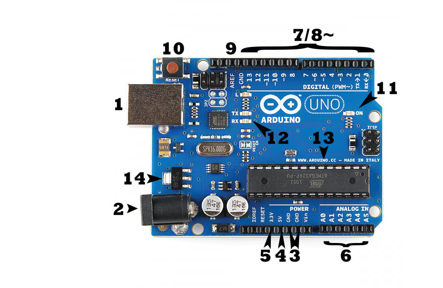
There are multiple types of Arduino boards intended for different purposes. Despite having some varying components on each board, these features are usually consistent across all types of Arduino boards:
USB/Barrel Jack
Every Arduino board needs access to power. This can be achieved through a USB cable connected from your computer to the board, or a power supply from the wall. In the above image, the USB port is labelled as (1), and the barrel jack (for wall power supply) is labelled as (2). An Arduino board is only capable of receiving power at a rate less than 20 volts. Any power supply higher than that can overpower and destroy the Arduino board. The recommended amount of power is between 6 and 12 volts. For loading code onto the Arduino board, the method to use is via USB cable.
Pins
Pins allow wires to be connected to the board to build circuits, usually used in conjunction with a breadboard and wire. The pins have black plastic ‘headers’ to enable the wires to slot right into the board. An Arduino board has a variety of pins, situated around the edges, which you can see in the image above labelled 3-9. These are:
- GND (Ground) - An Arduino has multiple GND pins (3), which are used to ground the circuit. A circuit is grounded when one of the conductive wires which is connected to the circuit is intentionally given a direct route to the Earth
- 5V (4) & 3.3V (5) - These pins are straightforward. One supplies 3.3V of power, and the other supplies five. Most components on an Arduino can run off either amount of power
- Analog (6) - You can see these pins in the above image, underneath the ‘analog in’ section. These pins can read the signal from an analog sensor and convert it into a readable digital figure
- Digital (7) - On the opposite side of the board, you can see the digital pins (0-13). These can be used for digital input and output
- PWM (8) - Some of the digital pins have a ‘~’ symbol next to them in the image above. These pins can be used for regular digital usage, but also have the power to be used for Pulse-Width Modulation (PWM). PWM is a method for achieving analog results with digital means
- AREF (9) - This refers to Analog Reference. A lot of the time, this isn’t used, but it can be used to set an external reference voltage as the maximum power for analog input pins
Reset Button
Pushing the reset button (10) temporarily connects the reset pin to ground and restarts any code that’s loaded onto the Arduino.
LED Power Indicator
Situated next to where it says ‘ON’ in the above image is an LED light. This should light up when the Arduino is connected to a power source and indicates that the board has power.
TX RX LEDs
TX (transmit) and RX (receive) indicate pins which enable serial communication. These signs are seen in the above image twice, next to digital pins 0 and 1 and then also by the TX and RX LED indicators (12). These LED indicators show when the Arduino is transmitting and receiving data.
Main IC
Short for integrated circuit, and can be seen in the above image (13). This is essentially the brain of the Arduino PCB. The ICs can vary from board to board, but it’s important that you know which one you’re using, as it will be a key piece of knowledge for loading a new program onto the board with the Arduino software. The type of IC is usually indicated on its surface.
Voltage Regulator
The voltage regulator (14) is important for maintaining the right amount of power being circulated through the board. It essentially turns away any excess power in order not to damage the Arduino. However, this is within reason and doesn’t mean you can connect it to any power source. The maximum should be 20 volts.
Types of Arduino PCB
The most recent type of Arduino is the Arduino Uno, which is the ideal PCB for beginners, containing everything required to get to grips with building electronic projects. However, there are many types of Arduino PCBs serving different purposes. It’s essential that you know which one to use for your specific project. Take a look below at some of the other members of the Arduino family:

LilyPad Arduino
The LilyPad Arduino is a microcontroller designed for e-textiles and wearable technology. The LilyPad’s flat back and large connecting pads allow it to be sewn into clothing with conductive thread. The Lilypad prevents snagging, is washable, and connects seamlessly with other devices.

Arduino Leonardo
The Leonardo is the first Arduino development board to use a microcontroller with a built-in USB. It’s based on the ATmega32u4 microcontroller and features 20 digital input/output pins (of which 7 can be used as PWM outputs), a microUSB connection, and a reset button. It’s powered with an AC/DC power supply and can be connected to a computer system directly through USB.

Arduino Mega
The Arduino Mega is the perfect option for projects which require a lot of pins, as the microcontroller has 54 input and output pins. PWM is enabled with 14 of these pins, whilst 16 serve as analog pins and four are intended for hardware port use. The board also boasts 256KB flash memory to store data in. It can be connected to a computer through a USB connection.

Arduino Nano
The Nano is the smallest board that you can build your projects with. The PCB features 22 digital input and output pins, of which six are capable of PWM. It also contains 32KB of flash memory for data. It works with a Mini-B USB cable instead of a standard one and has extremely low power consumption.
Arduino PCB Accessories
To fully incorporate the potential of Arduino, it needs to be connected to other components. Sensors and shields can be used to bring your projects to life.
Sensors
Arduino PCB can interact with a range of sensors, including light, temperature, pressure, proximity, humidity, and much more, just with some simple code.
Shields
Shields are pre-built circuit boards that can be mounted on the Arduino PCB to enable additional functionalities. Arduino shields can be used to control motors, connect to the internet, control an LCD screen, and lots more.
Advantages of Arduino PCB
Arduino PCB is a great tool to use for constructing and designing multiple electronic projects. Here are some reasons why Arduino PCB should be used:
- Cost-effective - Compared to alternatives, Arduino PCB is a cheaper and more practical option
- User-friendly - The circuit board is ideal for beginners and experts alike, thanks to its easy-to-use IDE
- Ready to use - The Arduino PCB is a complete package, coming with all the components you need to start designing projects, including an oscillator, serial communication interface, microcontroller, a burner, LED, and a 5V regulator
- Reliable - Whether designing either complex or simple electronic projects, Arduino PCB is a reliable choice. The boards already have soldered input and output ports
- Open-source software and hardware - The Arduino PCB open-source hardware allows users to build electronics projects easily, with various digital and analog pins. The software is easy to use, but can also be extended by programmers to expand the language via C++ libraries
- The Arduino Uno uses the ATmega328P microcontroller
- The Arduino Mega uses the ATmega2560 microcontroller
- The Arduino Nano uses the ATmega328 microcontroller
Is Arduino a Microcontroller?
Arduino itself is not a microcontroller. As mentioned before, it is an open-source electronics platform based on easy-to-use hardware and software. The Arduino board is a physical piece of hardware that includes a microcontroller as one of its many components. An Arduino board's microcontroller is a miniature computer on an integrated circuit that has programmable input/output peripherals, memory, and a central processing unit. As an illustration:
- The Arduino Uno uses the ATmega328P microcontroller
- The Arduino Mega uses the ATmega2560 microcontroller
- The Arduino Nano uses the ATmega328 microcontroller
Therefore, the Arduino platform comprises a microcontroller together with other components, including communication interfaces, power regulation, and an easy-to-use development environment.
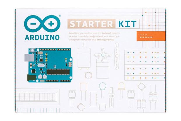
The Arduino Starter Kit
The Arduino Starter Kit is the best place to start for your very first Arduino project. The kit, which was created exclusively with novices in mind, takes you step-by-step through the fundamentals of using Arduino. Created around the Arduino UNO board, the kit comes with a book that will help you build a variety of inventive projects as you learn.
Also, you will be given a choice of the most popular and practical electronic parts, saving you the time and effort of looking up and choosing all the necessities. The kit will assist you in using sensors and actuators to control the real world, starting with the fundamentals of electronics and eventually progressing to more complicated projects. When the projects in the kit are finished, you'll have a selection of software, circuits, and - most importantly - knowledge that you can use to advance to more difficult tasks.