- Published 21 Nov 2025
- Last Modified 21 Nov 2025
- 6 min
The Problem of Intermittent Electrical Faults
Diagnose tricky electrical faults faster. Our guide explores how advanced oscilloscopes and signal analysers can help you solve complex circuit issues accurately.

An electrical fault is any disruption or interruption in a circuit’s electrical flow. This interferes with the circuit’s electrical devices performing properly. An intermittent fault happens infrequently and under very specific conditions. In a building, you might experience flickering lights, circuit breakers tripping often, or certain outlets failing - all seemingly erratically and unpredictably. On the automotive side of things, intermittent faults could include a failure to start, electrical systems failing during operation, and unexplained warning lights. The actual faults causing these can be things like short circuits, earth faults, loose connectors, contaminated solder, corroded battery terminals, or poor ground connections.
Intermittent faults are tricky and pesky to deal with. Since they only happen some of the time (due to things like temperature changes or specific loads on the system), it’s very hard to diagnose them and equally hard to prove that you’ve resolved the problem. An issue may happen during vehicle operation, for example, but then a technician may be unable to reproduce the issue and find the fault using standard circuit analysis tools when the vehicle is stationary in the shop.
Intermittent faults can indicate that a major component failure is developing or imminent, risking prolonged equipment downtime. A loose connection causing an intermittent fault can even turn into a shock or fire hazard. Resolving these faults is thus important to do promptly when they start showing themselves.
The Solution: Advanced Diagnostic Tools
Thankfully, advanced circuit analysis tools exist for detecting and diagnosing intermittent faults. Oscilloscopes assess how signals behave over time, while signal analysers (spectrum analysers) compare a signal’s amplitude against a range of frequencies. With these tools in hand, you can isolate signal glitches, dropouts, runts, interference, harmonics, and slow edges (all indicators of intermittent electrical faults) and learn more about what’s causing them.

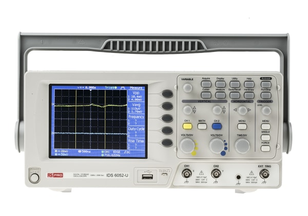
The Power of Oscilloscopes
Oscilloscope applications are widespread. They’re useful for testing and troubleshooting fibre optics, power grids, medical instruments, and vehicle electric systems. They’re also a powerful tool in intermittent electrical fault diagnosis.
By applying the oscilloscope’s measurement statistics features to signal wave data you’ve collected, you can easily see the maximum, minimum, mean, etc, values for things like wave amplitude or width. Those maximum and minimum values can indicate intermittent faults since they deviate from the mean so much. With that information, you can set automatic triggers on the oscilloscope to zoom data screens in on those irregular datapoints. This lets you study the fault in more detail, for example, by assessing motor speed, motor current, or temperature conditions at the time of the fault. Noting which other systems are running during the fault can also give you clues about its nature.
Some examples of signal irregularities include:
- Runts: If you have pulses with unacceptably low amplitudes, set the oscilloscope to trigger upon signals just above the minimum you experienced. So, if you want to ‘catch’ signals around the recorded minimum of 350 mV, set the trigger conditions to a maximum of 400 mV. Once a fault like that eventually occurs, this should give you a detailed snapshot of the intermittent fault you want to diagnose
- Glitches: If you’re experiencing pulses with very short durations, set the trigger limit to a pulse width slightly greater than the minimum width determined. So, if the minimum was 235 ns, set the oscilloscope to catch signals narrower than 250 ns
- Slow Edges: If signals’ slopes are the issue (their rise or fall times), then adjust the trigger conditions based on the slew rate. If the mean rise time is 40 ns but the maximum is 91 ns, set a trigger for rise times greater than 60 ns
- Drop-outs: If signals fail to capture for long periods, then set the trigger to capture these ‘drop-outs.’ Set the oscilloscope to trigger after a timeout of 50 µs if the longest timeout observed is 65 µs
All of these can require trial and error to see what the optimal trigger settings are for capturing an intermittent fault as it happens.
You can also use manual triggering to collect a small batch of data when you see an anomaly occur, though this depends on your reflexes (and you being there for the event). Also, the oscilloscope’s sample frequency, record length, and pre-trigger settings will affect the sample’s detail level and duration, so if these are set too low, you might not get enough useful information about the fault.
Signal Analysers and Their Applications
Signal analysers, also known as spectrum analysers, are a good complement to oscilloscopes. Rather than displaying a signal’s amplitude or other properties over time, they display how a signal’s amplitude changes over a range of frequencies. When it comes to diagnosing intermittent faults, spectrum analysers can identify problematic frequency issues like interference, harmonics, or any deviation of a signal’s frequency from its expected value.
Spectrum analysers are particularly useful for finding faults in the wiring of critical signals transmission: video broadcasts, Wi-Fi, telephone signals, and other telecommunications. All of these require clean, reliable transmitted signals. Given the increasingly complex and dynamic signals our everyday communications systems use, revealing any electrical faults in their transmission wiring is essential.
Real-time spectrum analysers (RSAs) are the best ones for hunting intermittent faults since they produce a complete picture of the signal without any dead time, which other analyser types exhibit due to the pauses in converting data rather than capturing it, as seen with snapshot Fast Fourier Transform (FFT) analysers. This requires a strong computational engine and memory buffer to achieve. RSAs can also have triggering capabilities, similar to oscilloscopes, letting you capture snapshots of specific fault conditions that can be rare to otherwise observe.
With an oscilloscope and a signal analyser, you can get a complete picture of the electrical signal that’s experiencing an intermittent fault. That can help lead you towards the fault’s cause, resolve it, and prevent the safety issues and equipment downtime of a major electrical failure.
A Step-by-Step Approach to Fault Finding
Once you have appropriate circuit analysis tools, here are some general steps for using them for intermittent electrical fault diagnosis:
- Find facts: Learn about the circumstances at fault events to get clues on fault causes. Ask questions of the people who noted the fault and find out how the equipment deviated from how it was supposed to be operating
- Measure and collect lots of data: Run the equipment through a few different controlled operating conditions so you have some baseline data to measure against and a large sample size to hopefully detect faults in. Collecting data of this scale is usually only an option for instruments connected to PCs (and their large hard drives), since the instruments themselves can have low buffer memories
- Find the worst-case conditions in the assessment period: Determine the maximum and minimum signal widths, amplitudes, etc, which may indicate intermittent faults
- Collect more data, but triggered on those conditions: Set the instrument to only collect data when signals appear in the range of the irregular datapoints. If you’ve collected data on a PC, you can just zoom in on those points without needing to set up triggers
- Analyse the results: With this data focused on the moment of the intermittent fault, assess the system conditions before and after that moment to try to determine what caused this problem and why. This should eventually lead you to the problematic component causing the fault
With these tools and tips, you can identify intermittent faults and correct them before they cause major failures. If you need circuit analysis tools for simpler, more constant electrical fault diagnosis, browse our range of multimeters today.

Related Articles
Related links
- Eaton Memshield RCBOs
- Electronics Cleaning Chemicals: Solving Common Challenges & Their Solutions
- Electronics Adhesives: Solving Common Bonding & Sealing Issues
- Solder Flux Types: Troubleshooting Common Soldering Issues
- Maintenance Using Vibration Analysis and Condition Monitoring
- Seven challenges facing engineers in MRO today
- RS Maintenance Solutions
- Optimising Supply Chains with Digital Twins