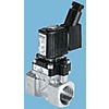
Burkert Solenoid Valve 140844, 2 port(s) , NC, 24 V ac, 3/8in
- RS Stock No.:
- 370-0084
- Mfr. Part No.:
- 140844
- Brand:
- Burkert


Image representative of range
Currently unavailable
We don't know if this item will be back in stock, RS intend to remove it from our range soon.
Alternative
This product is not currently available. Here is our alternative recommendation.
Each
£72.40
(exc. VAT)
£86.88
(inc. VAT)
- RS Stock No.:
- 370-0084
- Mfr. Part No.:
- 140844
- Brand:
- Burkert
Specifications
Technical Reference
Legislation and Compliance
Product Details
Find similar products by selecting one or more attributes.
Select all | Attribute | Value |
|---|---|---|
| Brand | Burkert | |
| Supply Voltage | 24 V ac | |
| Number of Ports | 2 | |
| Connection Size | 3/8in | |
| Connection | 3/8 in G Female | |
| Operation | Pilot | |
| Default Valve Position | NC | |
| Suitable Applications | Liquid, Neutral Gas | |
| Type | 2/2 | |
| Orifice Diameter | 10mm | |
| Series | 6211 | |
| Body Material | Brass | |
| Maximum Working Pressure | 10 bar | |
| Operating Temperature Range | 0 → +55 °C | |
| Servo Assist | Yes | |
| Maximum Operating Temperature | +55°C | |
| Connection Gender | Female | |
| Thread Standard or Connection Type | G | |
| Minimum Operating Temperature | 0°C | |
| Maximum Opening Time | 240ms | |
| Flow Factor Kv | 1.9m³/h | |
| Maximum Closing Time | 130ms | |
| Select all | ||
|---|---|---|
Brand Burkert | ||
Supply Voltage 24 V ac | ||
Number of Ports 2 | ||
Connection Size 3/8in | ||
Connection 3/8 in G Female | ||
Operation Pilot | ||
Default Valve Position NC | ||
Suitable Applications Liquid, Neutral Gas | ||
Type 2/2 | ||
Orifice Diameter 10mm | ||
Series 6211 | ||
Body Material Brass | ||
Maximum Working Pressure 10 bar | ||
Operating Temperature Range 0 → +55 °C | ||
Servo Assist Yes | ||
Maximum Operating Temperature +55°C | ||
Connection Gender Female | ||
Thread Standard or Connection Type G | ||
Minimum Operating Temperature 0°C | ||
Maximum Opening Time 240ms | ||
Flow Factor Kv 1.9m³/h | ||
Maximum Closing Time 130ms | ||
- COO (Country of Origin):
- DE
6211 series NF 2/2 power-assisted solenoid valves
6211 series solenoid valves are NF 2/2 power-assisted valves with separation membranes.
Used for neutral fluids such as gas, air, water and oils, liquids that do not contain oils or greases, hot water up to 70 °C, alkaline and bleaching lyes.
Used for all or nothing control.
Used for neutral fluids such as gas, air, water and oils, liquids that do not contain oils or greases, hot water up to 70 °C, alkaline and bleaching lyes.
Used for all or nothing control.
Compact solenoid valves suitable for most gas and fluid handling applications. Where practical, valves are shown with a schematic diagram showing the (circuit) function. The diagram is laid out so that the left-hand side of the diagram describes the valves operation when the coil is energised. When the coil is de-energised, the spring (or servo-assist) return controls the valve and is described on the right-hand side of the diagram. The 3 / 2-way designation indicates a valve with three ports and two modes of operation. It is normal practice to refer to 2 / 2-way valves as two ways. The port designations A, B, P, P1, P2 and R are used on the schematic diagrams and are marked on the valve bodies. Valve bodies are marked for a specific circuit function but can often be used for other functions. Reference to the schematic diagrams and technical specifications indicates the appropriate connections and pressure capabilities when an alternative circuit function is required.
Related links
- Burkert Solenoid Valve 221599 NC 3/8in
- Burkert Solenoid Valve 221600 NC 3/8in
- Burkert Solenoid Valve 221760 NC 3/8in
- Burkert Solenoid Valve 221601 NC 3/8in
- Burkert Solenoid Valve 140846 NC 3/8in
- Burkert Solenoid Valve 221761 NC 3/8in
- SMC Solenoid Valve VXZ262KZ1VA NC 3/8in
- SMC Solenoid Valve VXZ252HZ1VA NC 3/8in