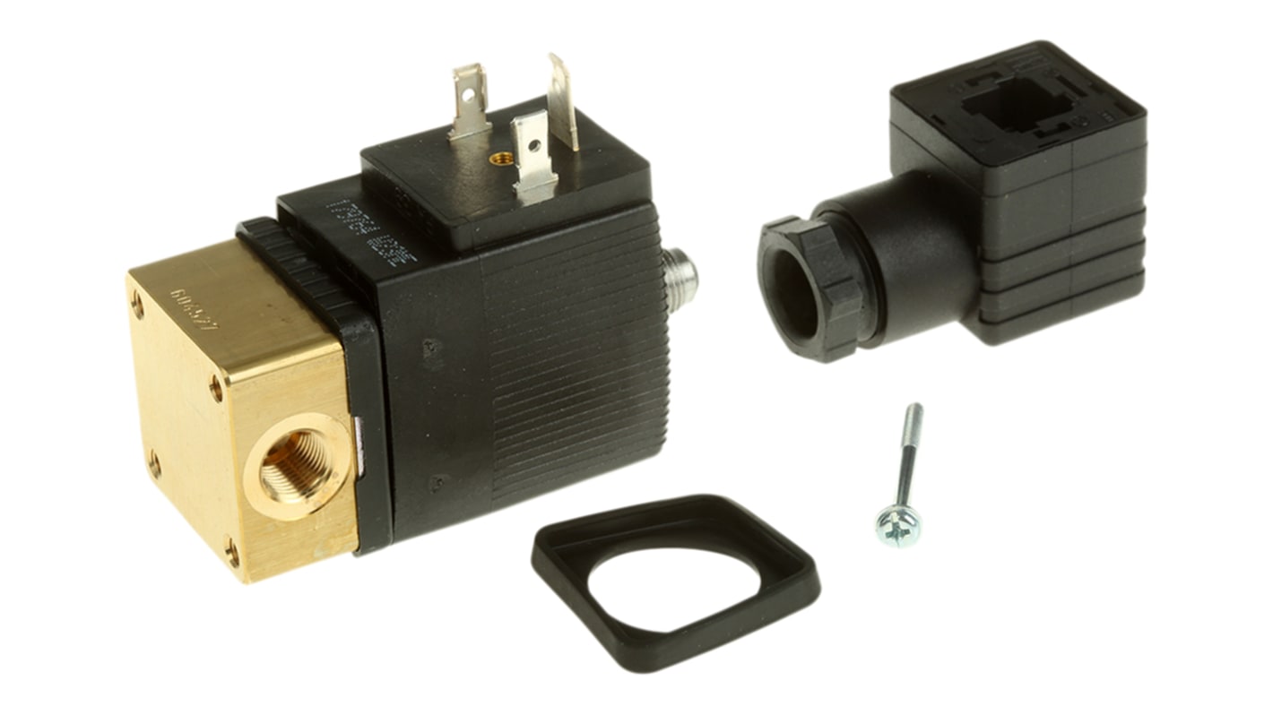
Burkert Solenoid Valve 125335, 3 port(s) , NC, 110 V ac, 1/8in
- RS Stock No.:
- 439-010
- Mfr. Part No.:
- 125335
- Brand:
- Burkert

Bulk discount available
Subtotal (1 unit)*
£75.04
(exc. VAT)
£90.05
(inc. VAT)
FREE delivery for orders over £50.00
In Stock
- 12 unit(s) ready to ship
Need more? Click ‘Check delivery dates’ to find extra stock and lead times.
Units | Per unit |
|---|---|
| 1 - 4 | £75.04 |
| 5 + | £72.72 |
*price indicative
- RS Stock No.:
- 439-010
- Mfr. Part No.:
- 125335
- Brand:
- Burkert
Specifications
Technical Reference
Legislation and Compliance
Product Details
Find similar products by selecting one or more attributes.
Select all | Attribute | Value |
|---|---|---|
| Brand | Burkert | |
| Supply Voltage | 110 V ac | |
| Number of Ports | 3 | |
| Connection Size | 1/8in | |
| Connection | 1/8 in G Female | |
| Operation | Direct | |
| Default Valve Position | NC | |
| Suitable Applications | Air, Gas, Neutral Liquid, Oil, Oil without Additives, Water | |
| Type | 3/2 | |
| Orifice Diameter | 2mm | |
| Body Material | Brass | |
| Series | 6014 | |
| Maximum Working Pressure | 10 bar | |
| Operating Temperature Range | -10 → +100 °C | |
| Maximum Operating Temperature | +100°C | |
| Connection Gender | Female | |
| Minimum Operating Temperature | -10°C | |
| Thread Standard or Connection Type | G | |
| Flow Factor Kv | 0.11m³/h | |
| Select all | ||
|---|---|---|
Brand Burkert | ||
Supply Voltage 110 V ac | ||
Number of Ports 3 | ||
Connection Size 1/8in | ||
Connection 1/8 in G Female | ||
Operation Direct | ||
Default Valve Position NC | ||
Suitable Applications Air, Gas, Neutral Liquid, Oil, Oil without Additives, Water | ||
Type 3/2 | ||
Orifice Diameter 2mm | ||
Body Material Brass | ||
Series 6014 | ||
Maximum Working Pressure 10 bar | ||
Operating Temperature Range -10 → +100 °C | ||
Maximum Operating Temperature +100°C | ||
Connection Gender Female | ||
Minimum Operating Temperature -10°C | ||
Thread Standard or Connection Type G | ||
Flow Factor Kv 0.11m³/h | ||
- COO (Country of Origin):
- DE
6014 General Purpose Solenoid Valve
Brass bodied, normally closed solenoid valves.
Coil changed easily with valve in place
Two female ports and a 1/8 in. male vent port
Coil can be locked in four by 90° positions or move free between, as required
Brass body and FKM high quality seal material
Epoxy encapsulated coil
Fluid temperature range: -10 to +90°C
Suitable for use with water, neutral fluids air natural, gases, oil and fats (without additives)
Maximum viscosity: 21mm2/s
Operating temperature: –10 to +100°C max.
Power consumption: 21VA (a.c. in rush), 12VA/8W (constant) 8W (d.c.)
Protection to IP65 with cable plug DIN43650C
3 Way Inert Gases and Fluid Valves
Compact solenoid valves suitable for most gas and fluid handling applications. Where practical, valves are shown with a schematic diagram showing the (circuit) function. The diagram is laid out so that the left hand side of the diagram describes the valves operation when the coil is energised. When the coil is de-energised, the spring (or servo-assist) return controls the valve and this is described on the right hand side of the diagram, see the typical schematic diagram below.,The 3//2-way designation indicates a valve with three ports and two modes of operation. It is normal practice to refer to 2//2-way valves as two-way.,The port designations A, B, P, P1, P2 and R are used on the schematic diagrams and are marked on the valve bodies. Valve bodies are marked for a specific circuit function but can often be used for other functions. Reference to the schematic diagrams and technical specifications will indicate the appropriate connections and pressure capabilities should an alternative circuit function be required.
Related links
- Burkert Solenoid Valve 126093 NC 1/8in
- Burkert Solenoid Valve 425304 NC 1/8in
- Burkert Solenoid Valve 125336 NC 1/8in
- Burkert Solenoid Valve 125368 NC 1/8in
- Burkert Solenoid Valve 125338 NC 1/8in
- Burkert Solenoid Valve 125334 NC 1/8in
- Burkert Solenoid Valve 125374 NC 1/8in
- Burkert Solenoid Valve 125370 NC 1/8in