Burkert Solenoid Valve Three Part Connector Set for use with 6228 Solenoid Valve
- RS Stock No.:
- 388-4980
- Mfr. Part No.:
- 142426
- Brand:
- Burkert

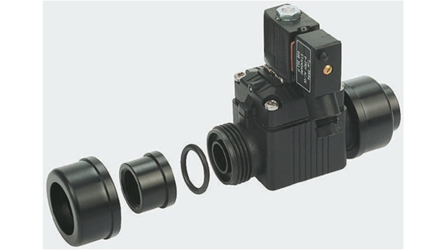
Image representative of range
Bulk discount available
Subtotal (1 unit)*
£8.69
(exc. VAT)
£10.43
(inc. VAT)
FREE delivery for orders over £50.00
In Stock
- 9 unit(s) ready to ship
- Plus 5 unit(s) ready to ship from another location
Need more? Click ‘Check delivery dates’ to find extra stock and lead times.
Units | Per unit |
|---|---|
| 1 - 4 | £8.69 |
| 5 - 9 | £8.30 |
| 10 - 24 | £8.14 |
| 25 + | £7.97 |
*price indicative
- RS Stock No.:
- 388-4980
- Mfr. Part No.:
- 142426
- Brand:
- Burkert
Specifications
Technical Reference
Legislation and Compliance
Product Details
Find similar products by selecting one or more attributes.
Select all | Attribute | Value |
|---|---|---|
| Brand | Burkert | |
| Accessory Type | Three Part Connector Set | |
| For Use With | 6228 Solenoid Valve | |
| Select all | ||
|---|---|---|
Brand Burkert | ||
Accessory Type Three Part Connector Set | ||
For Use With 6228 Solenoid Valve | ||
RoHS Status: Exempt
- COO (Country of Origin):
- DE
6228 Series 2//2-way Plastic Solenoid Valve
Servo-assisted 2//2-way normally closed solenoid valve
For general purpose applications - including water and sewage treatment, distribution and irrigation systems, dosing, filling and batching
Compact and lightweight
Low power consumption
0.5 to 10 bar pressure range
Servo diaphragm seal: FPM Body in PPE/PA
Unique pipe connection system allows ease of replacement for maintenance applications
Neutral fluids with a maximum temperature of 50°C that will not affect the plastic material e.g. pressurized air, water, hydraulic oils, oils or fat without additives
Ambient temperature 55°C max.
Note
2 pipe connectors required per valve
Compact solenoid valves suitable for most gas and fluid handling applications. Where practical, valves are shown with a schematic diagram showing the (circuit) function. The diagram is laid out so that the left-hand side of the diagram describes the valves operation when the coil is energised. When the coil is de-energised, the spring (or servo-assist) return controls the valve and is described on the right-hand side of the diagram. The 3 / 2-way designation indicates a valve with three ports and two modes of operation. It is normal practice to refer to 2 / 2-way valves as two ways. The port designations A, B, P, P1, P2 and R are used on the schematic diagrams and are marked on the valve bodies. Valve bodies are marked for a specific circuit function but can often be used for other functions. Reference to the schematic diagrams and technical specifications indicates the appropriate connections and pressure capabilities when an alternative circuit function is required.
Related links
- Burkert Solenoid Valve Three Part Connector Set for use with 6228 Solenoid Valve
- Burkert Solenoid Valve 4-Way Manifold for use with 6014 Solenoid Valve
- Burkert Solenoid Valve Cable Plug for use with 2518 Solenoid Valve
- Burkert Solenoid Valve 5-Way Manifold for use with 6011 Solenoid Valve
- Burkert Solenoid Valve 1-Way Manifold for use with 6014 Solenoid Valve
- Burkert Solenoid Valve 2-Way Manifold for use with 6011 Solenoid Valve
- Burkert Solenoid Valve 1-Way Manifold for use with 6011 Solenoid Valve
- Burkert Solenoid Valve 4-Way Manifold for use with 6011 Solenoid Valve