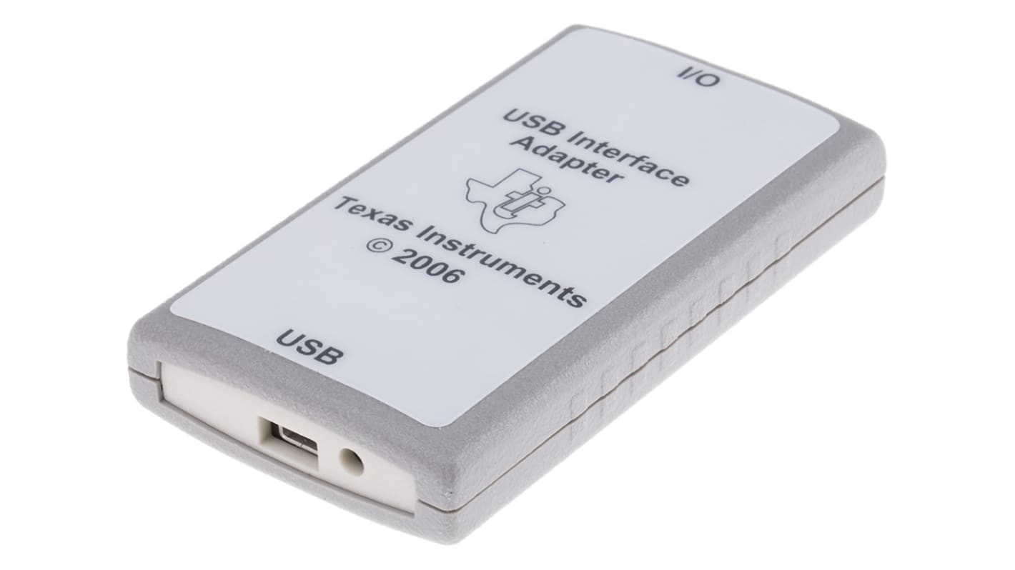
Texas Instruments Development Kit USB-TO-GPIO
- RS Stock No.:
- 819-7562
- Mfr. Part No.:
- USB-TO-GPIO
- Brand:
- Texas Instruments

Unavailable
RS will no longer stock this product.
- RS Stock No.:
- 819-7562
- Mfr. Part No.:
- USB-TO-GPIO
- Brand:
- Texas Instruments
Specifications
Technical Reference
Legislation and Compliance
Product Details
Find similar products by selecting one or more attributes.
Select all | Attribute | Value |
|---|---|---|
| Brand | Texas Instruments | |
| Kit Classification | Development Kit | |
| Select all | ||
|---|---|---|
Brand Texas Instruments | ||
Kit Classification Development Kit | ||
USB Interface Adapter Evaluation Module
Texas Instruments USB-TO-GPIO USB Interface Adapter Evaluation Module serves as an interface adapter or a bridge between a host PC (IBM™ compatible) and one or multiple slave devices via a standard type-A to mini-B USB cable. The communication between the USB interface adapter and the host PC is via USB, while the communication between the USB interface adapter and the slave device(s) is via an inter-integrated circuit (I²C), SMBus, PMBus and/or general-purpose inputs/outputs GPIOs. The bridge converts communication transactions between the USB and serial protocol.
Supports master mode I²C, SMBus or PMBus as well as GPIO.
Supports USB1.1 full speed at 12 Mbit/s. The USB interface adapter is recognized by the host as a generic human interface device (HID), so no proprietary USB or HID driver is needed. Therefore, the USB interface adapter can be treated as a USB plug-and-play device.
Selects different clock speeds (either 100 kHz or 400 kHz) for I²C, PMBus, or SMBus communications.
Configures different pullup resistors for clock, data and ALERT signals (including open-drain).
Supports flexible I²C read or write transactions (specify raw data, instead of device address, command, etc.) .
Includes .NET DLL for supporting Windows .NET GUIs using the adapter.
No Windows dependencies other than the Microsoft .NET Framework version 2.0
The IEEE 1149.1 standard test access port and boundary-scan architecture uses devices known by the JTAG acronym, from Joint Test Action Group, and is used for testing and debugging system ports and PCB assemblies. Most embedded systems employ JTAG ports to enable in-circuit debugging and firmware programming, in addition to boundary scan testing.
