- Published 23 Apr 2023
- Last Modified 9 Aug 2023
- 6 min
What is Insulation Resistance?
This guide will explain insulation resistance - what it is and the various tools and equipment you can use to test and measure it.

Insulation resistance is a term applied to the measured value in Ohms of an insulating material surrounding electrical conductors such as cables. Electric current can flow either directly through the surrounding insulator material or around its surface. The amount of current flow will depend on the magnitude and the nature of the voltages being used. The higher the voltage, the more challenging it will be to provide adequate insulation between conductors and any other surrounding objects where the current flow from the conductor is not wanted.
Excessive unwanted current flow from the conductor via the insulator can cause many problems such as short circuits, flash arcing, overheating, fire, and electrocution. Therefore, being able to test insulation resistance is crucial in ensuring that you maintain a safe environment in all types of settings where electrical equipment is used.
Having the ability to measure insulation resistance will enable you to pre-empt any potential equipment failures. Testing should significantly reduce the risk of possible failures due to insulation breakdown.
What is Insulation Resistance Testing?

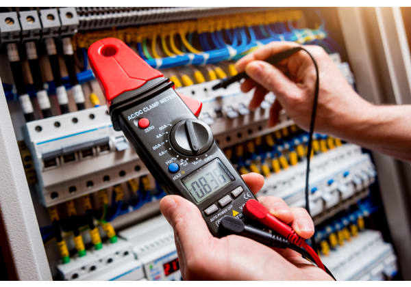
An insulation tester or Megohmmeter can be used to determine the insulation resistance of a cable, installation, motor, or appliance. The principle is to apply a known DC voltage and then measure the flowing current. Ohm’s Law would then apply in deriving an effective DC resistance.
Ohm's law states - the voltage across a conductor is directly proportional to the current flowing through it if physical conditions and temperatures remain the same. In the equation, Resistance is R, and has units of Ohms, with the symbol Ω.
The value of insulation resistance measured is important. The minimum acceptable value for most applications is to have more than 1 megohm (million Ohms) for every 1000 volts of the intended operating voltage. Modern <u>insulation testers</u> have digital readouts and work by applying high voltages to conductors that are insulated.
You should perform high-voltage insulation resistance testing on a systematic and regular basis. A good reason for doing this is that the insulating material tends to break down over time and with use. This is particularly important on portable equipment. Insulation resistance can change over time due to:
- Temperature
- Movement such as flexing or bending
- Chafing
- Humidity
- Age (degradation with time)
- Ultraviolet light
PAT Continuity and Testing Insulation Resistance
PAT (portable appliance testing) is carried out on electrical equipment to enhance user safety using a pat tester. The full test involves several processes.
- Insulation resistance test
- Visual inspection, checking for correct fuse value, insulation damage, and fraying copper strands at the connection point
- Earth continuity test
- Polarity test
The PAT testing insulation resistance limits are 1 megohm (1 million Ohms) for every 1000V of intended use. For example, if we were to expect an insulated conductor to operate at 5000V then we would expect the insulation resistance value for that cable to be over 5 megohms.
There are three categories of domestic electrical appliances:
- Class 1 (has live neutral and earth)
- Class 2 (has live and neutral and no earth, usually a double insulated appliance)
- Class 3 (Low voltage appliance less than 50V)
Let's assume that we would like to PAT test a Class 1 appliance. We would:
- Plug the appliance into the PAT tester socket
- Connect the flying earth probe to the appliance's metal body
- Press the Class 1 test button
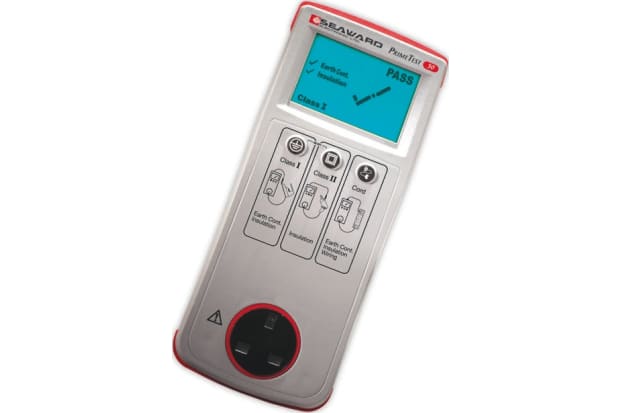
The PAT tester would then display earth continuity, insulation resistance and load leakage on the display indicating either pass or fail.
You would then record the results on an equipment inspection and test record and a pass-fail sticker would be applied to the appliance that has been tested.
There are many <u>PAT tester accessories</u> available such as printers, labels, and cable attachments.
Insulation Resistance Testing Procedure
Testing insulation resistance is one of the tests we perform during a PAT test, but it can be performed on its own. One example is when testing insulation resistance cables in an industrial electrical installation.
How to Test Insulation Resistance
You can carry the test out by using an insulation tester, such as a Megger device. Using the domestic installation example, a test of insulation effectiveness can be carried out when the mains supply is isolated. Insulation resistance can be determined between live, neutral and earth connections with no loads or appliances connected to any sockets or wiring. Any problems would be shown by a lower-than-expected resistance being present between them. In domestic wiring anything above 2 megohms is acceptable.
IEC Standard for Insulation Resistance Testing
There are several IEC (International Electrotechnical Commission) documents about electrical testing including insulation resistance testing. One such document, IEC 60364-6 requires that a test voltage of 500V DC shall result in an insulation resistance of at least 1 megohm. The following table indicates figures derived from the IEC 60364-6 document.
Nominal circuit voltage | Test voltage DC | Insulation resistance |
|---|---|---|
| Less than 50V AC or less than 120V DC | 250V | Greater than 0.5 megohms |
| Up to 500V | 500V | Greater than 1 megohm |
| Above 500V | 1000V | Greater than 1 megohm |
Motor Insulation Resistance Testing
For electric motors, the insulation resistance is measured between the windings and the frame. For a good motor, you would expect to see 10 megohms or more. As the motor ages, the value of insulation can depreciate to lower values due to dust, dirt, moisture, loose armature, and other factors.
A general rule when measuring motor insulation resistance is as follows.
- 2 megohm or less (bad) 2 to 5 megohm (critical)5 to 10 megohm (suspect) 10 to 50 megohm (good) Above 50 megohm (excellent)
Transformer insulation resistance testing is carried out similarly but is more complex due to the nature and construction of transformers. The insulation resistance is carried out from each winding to earth or ground as well as between windings.
Often industrial transformers are manufactured to operate at very high voltages so high-voltage insulation resistance testing is often needed. Several thousand volts are applied to test for high voltage leakage and insulation breakdown. These systems can typically operate at 5000V and over.
We hope you have found our guide on PAT testers and insulation testers informative and useful.