- Published 30 Aug 2023
- Last Modified 26 Jan 2024
- 6 min
What is Power Factor Correction (PFC)?
If you have high utility costs due to a low power factor in your electrical systems, RS power factor correction devices can come to the rescue. Learn about how PFC balances out a circuit’s reactive power to bring down heat and waste and crank up efficiency and equipment life.

Reviewed by Stephen Bettles, Technical Support Engineer (August 2023)
Power factor correction (PFC) betters the efficiency, or power factor, of an AC electrical system. To determine your power factor, divide your system’s active power by its apparent power.
- The active power is the on-paper power needed for doing the circuit’s work, such as turning motors
- Reactive power doesn’t get put to useful work and instead bounces back to the power supply
- In a 90-degree triangle plot of the active power and reactive power, the apparent power is the longest edge
Ideally, the power factor will be one (100% efficiency), and you can get closer to this goal using RS Power Factor Correction devices
Why is Power Factor Correction Required and How is it Achieved?
Electrical utility providers often charge extra to industrial or commercial businesses with a power factor below around 0.9 since reactive power is a waste of generated power. In this case, PFC is required to see fewer electricity cost penalties for your business.
There are additional reasons too, such as increasing the lifespan of your equipment and having more useful power available for it.
PFC generally involves capacitors releasing built-up energy against the direction of reactive power that loads would otherwise unnecessarily circulate through the system.
Each capacitor is ideally placed close to the load it’s meant to react against. However, larger capacitors can be sized and placed to handle groups of loads. This can depend on your system’s space and cost limitations.
Power Factor Correction Circuit

This shows a simple AC circuit before and after PFC. The resistor and inductor represent a motor’s shaft and magnetic field, respectively. The added capacitor’s reactive power will counteract the power ‘wasted’ on creating the (necessary) magnetic field with the inductor.
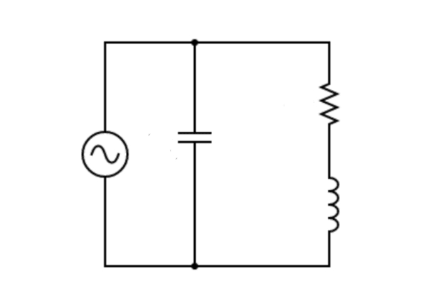
Once the capacitor’s PFC is in place, the circuit’s voltage and current become more in phase with each other and the power factor becomes closer to 1. This demonstrates the advantages of power factor correction in an RLC circuit (resistor-inductor-capacitor).
How to Calculate Capacitor Value for Power Factor Correction
To find the amount of PFC your system needs, use a power quality analyser to directly measure a circuit’s power factor. You can also use the power factor correction calculation formula:
Qc = P (tan ϕ – tan ϕ')
- Qc is the total reactive power (kVAr)
- P is the Active Power (kW)
- ϕ is the initial phase shift angle
- ϕ' is the compensated phase shift angle
The phase shift angle is the timing difference between the system’s current and voltage. It is the horizontal offset in the plots in the PFC circuit example above, and it too can be measured with a power quality analyser.
Once you’ve determined the total reactive power, you’ll need to determine how to achieve that in capacitors: either individual ones next to their loads (ideal), or larger ones handling groups of loads, which may be necessary based on your system’s constraints.
If you don’t have the values for this power factor correction calculation, you’ll need to perform the detailed circuit calculations, which will vary with circuit complexity. For the above simple PFC circuit example, use the resistor’s Ohm value, the inductor’s Henry value, and the source’s Volt and Hertz values to determine the capacitor’s required Farad value.
Types of Power Factor Correction Techniques and Devices
PFC can be achieved through multiple techniques using various types of technology - capacitor banks, static var compensators (SVCs), active power factor correction (APFC), and hybrid power factor correction (HPFC).
Capacitor Banks
A capacitor bank is a package of capacitors built into a single unit. These capacitors can be in series or parallel depending on the application.
They are used most prominently in electric power distribution to counteract the inductive loads of transmission lines. These banks become very large units to handle equally large loads.
Capacitor banks come in all sizes for all types of applications, including for reducing charging time on smartphones.
Static Var Compensators (SVCs)
A static var compensator (SVC) is a PFC device that responds automatically to a system’s decreasing power factor whether it’s the voltage or the current coming out of balance.
An SVC contains a thyristor-controlled reactor that responds to capacitive (leading) reactive power and a capacitor for absorbing an inductive (lagging) reactive power.
The adaptable nature of SVCs makes them a good choice for responding to surges in a circuit’s impedance.
Active Power Factor Correction (APFC)
Active Power Factor Correction (APFC) is employed in most power factor correction devices. More involved and complex than a simple capacitor or a capacitor bank, APFC units contain circuitry to measure the reactive power conditions of a circuit and respond accordingly. They can be built in very small, compact sizes.
These internal PFC features include voltage regulators, overvoltage detectors, zero current detectors, and input undervoltage lockout. Browse our APFC datasheets to learn more about the detailed PFC benefits they offer, and which units will fit best in your system.
Hybrid Power Factor Correction
Along with poor power factors, circuits can also have poor power quality due to harmonics, which can damage equipment. Hybrid power factor correction addresses both issues at once, using standard PFC, such as capacitor banks, to address reactive power, and active harmonic filtration (AHF) to remove system harmonics.
Hybrid power factor correction systems can also combine PFC methods. They can deploy APFC for a system’s unsteady, dynamic, charging periods while relying on capacitors for steady, static operation. This avoids constant APFC use, which can generate considerable heat.
The Benefits of Power Factor Correction
PFC offers benefits on many fronts - reduced energy usage and utility penalties, cooler running systems, longer-lasting components, less downtime, and better safety.
Energy Efficiency and Reduced Electricity Costs
Reactive power represents electric power that was generated but not put to good use. For this reason, utility providers often apply financial penalties to businesses that fail to keep their power factors above 0.9.
PFC also generally increases circuit efficiency due to reducing voltage drop in long cables, lowering heat loss, and being able to use more of the supplied power for useful work.
Utility penalties, coupled with increased energy usage due to reactive power, demonstrate the business benefits of implementing power factor correction. You will save costs and help the environment by using less energy unnecessarily.
Equipment Lifespan and Reduced Risk of Failure
In addition to improving energy efficiency, PFC improves the health of your system’s components, chiefly through reduced heat generation due to drawing less current. Equipment running hotter will have a reduced lifespan and can even present a fire hazard.
The drastic steps in voltage that come with reactive power can damage components sensitive to voltage changes. PFC can thus reduce your risk of component failure, giving you fewer headaches in terms of increased maintenance.
Our power factor correction devices, along with our other Power Management Integrated Circuit products, can make your electrical systems efficient, long-lasting, and safe.