- Published 23 Apr 2023
- Last Modified 29 Aug 2023
- 5 min
What is a Comparator?
A comparator is an effective way of measuring the differences in strength between two currents.

Comparators form an essential function of many electronic devices, and this guide will let you know what they do, how they work and their benefits.
What Does a Comparator Do?
There is a tool for virtually every measurement that needs to be taken, and this is no different for measuring voltage in electricity. Where comparators are concerned, the clue is in the name as a comparator is designed to take in two voltages, and then tell the user of the device which is the highest voltage.
How Does a Comparator Work?
The principles and design of a comparator are fairly straightforward: two currents are sent through the comparator, they are read and then the output is given on which has the highest voltage current. The currents inputted to a comparator are an inverting input and non-inverting input.
This may also be referred to as a negative and positive input, the inverting being the negative and the non-inverting being a positive input. The output of a comparator will read high or low, based on whichever is the highest voltage current. High will indicate a positive voltage current and low indicates a negative. These readings are also expressed in binary, with 0 being a low or negative voltage and 1 being a high or positive voltage. The outputs of a comparator can also be expressed in the following equations: Vo=1 when V+>V–, or Vo= 0 when V+<V–.
The comparator works by amplifying the differences in the voltage between the two inputs, allowing it to better read the strongest voltage current and produce an output. The device that performs the amplification is called a high-gain differential amplifier.
Comparator Use
Having learnt the science, the next question may be how they are used in a practical setting. Comparators are a very versatile tool and can be used in a range of ways, the first of these being a zero crossing detector. This device is used for the purpose of tracking the sine waveform (a waveform that moves up and down) as it moves between a negative and positive voltage current. They are commonly used in the monitoring of power circuits, as well as in modems and other household devices.
Another way that comparators can be used is in relaxation oscillators. These devices can be found in indicators, blinking lights and even inverters and their purpose is to output a repeating signal. The waveform of this comparator is a triangle shape (and can sometimes be square-shaped) and is known as a non-sinusoidal periodic waveform.
A third way comparators can be used is in analogue to digital converters. These devices convert analogue signals to digital readings, as well as give a digital reading on a voltage current. Due to their versatility, they are used in a wide range of devices, such as mobile phones, mobile applications, audio devices and image devices, such as digital cameras.
They are also used in window detectors. These detectors make use of two comparators. Their outputs flow into an AND logic gate, to measure currents and detect unknown patterns. These detectors are primarily used in safety equipment such as industrial alarms, product testing on a production line and level sensors. They are also present in digital computers.
A final way to use a comparator is in a null detector, also known as a null instrument. These devices are designed to detect a null voltage in a device, and can also be used in a similar way to a galvanometer, which measures the voltage or current in a device.
Types of Comparators
As with most types of technology, there are also variants of this component, depending on the need or use. The first of these is called an inverting comparator. These are comparators that have previously been discussed and use operational amplification when comparing voltages. The inverting comparator compares a reference voltage to an input voltage to produce its output, and that input voltage is placed on the inverting terminal of the amplifier; this is how the inverting comparator gets its name.
The second type of electronic comparator is the non-inverting comparator. This comparator works in a reverse way to the inverting comparator. On this device, there is an operational amplifier, a reference circuit and an input circuit. However, unlike the previous comparator, the input circuit is placed on the non-inverting terminal, and the reference circuit is placed on the inverting terminal. Even so, the diagram of a non-inverting comparator looks the same as an inverting comparator, with two inputs and one output.
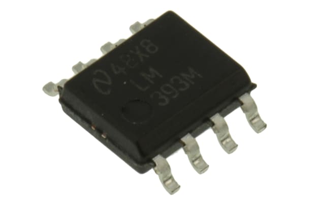
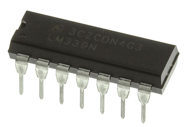
The final type of comparator is the LM324 OP-AMP. This device contains four comparators on one chip, allowing you to run and compare multiple circuits on one device. For this device, the inverting current is placed on a negative input, whilst the non-inverting current is placed on a positive input; this is the case for all four comparators that make up the device. Like the non-inverting and the inverting comparator, each of the comparators within this chip works on the basis of taking two inputs to produce one output.
Advantages of Comparators
There are many advantages to the use of electronic comparators, the first being its lack of moving parts. Because a comparator largely relies on current, signal and digital output, this means that they have fewer moving parts and therefore are less likely to malfunction, making them more budget-friendly and long-wearing.
Comparators are also extremely sensitive and are able to read even the slightest changes in currents, meaning that they are extremely accurate and reliable in situations where safety monitoring is their primary purpose.
Finally, comparators come in a range of sizes and are simple in function and installation, meaning that they are extremely versatile, with plenty of functionality.