- Published 3 Feb 2023
- Last Modified 29 Aug 2023
- 7 min
A Complete Guide to Rotary Switches
Our guide focuses on rotary switches, explaining their uses, how they work, and the different types available.

What is a Rotary Switch?
Rotary switches can be explained relatively easily. Many devices and circuits require switches with multiple available positions, to select different electrical circuits or states within a device. As the name suggests, they move between these positions via rotation.
As conventional switches can normally access only two positions (e.g. on or off), complex configurations or devices might require multiple switches. A rotary switch provides a simpler, all-in-one solution.
Rotary switches are classed as human-machine interface (HMI) components because they provide a way for operators to interact with and control equipment.
Multiple configurations are available for different settings, and a wide range of accessories are also available.
What are Rotary Switches Used for?
Rotary switches are used to connect a functional circuit within a device to a source of electricity. The electrical charge enters the switch and is then directed to whichever circuit is currently selected by the switch.
Rotary switches provide a robust, mechanical control system with immediate tactile feedback, in contrast to software-based systems such as touch screens. In some settings, software errors could be hazardous or cause significant issues.
Amongst the most familiar rotary switch applications are:
- Variable speed fans
- Rotary light switches
- Rotary lamp switches
- Dimmers
You will also find rotary switches in:
- Professional audio splitters and converters - for moving between different speakers or channels
- 3-way and 6-position rotary switch guitars - for selecting different tones and effects
- Handheld radios - for moving between different channels and bands
- Voltmeters and similar metering equipment - for selecting different ranges
- Car dashboards - for selecting different functions such as the air conditioning or adjustable fans
- Aircraft control panels
They are also used on a wide range of industrial, medical, construction, and military communications equipment, for example:
- To adjust the speed of conveyor belts
- To adjust the frequency of oscilloscopes
- To control diagnostic equipment
Rotary switches are often used with circuitry that needs to move seamlessly between complex configurations.
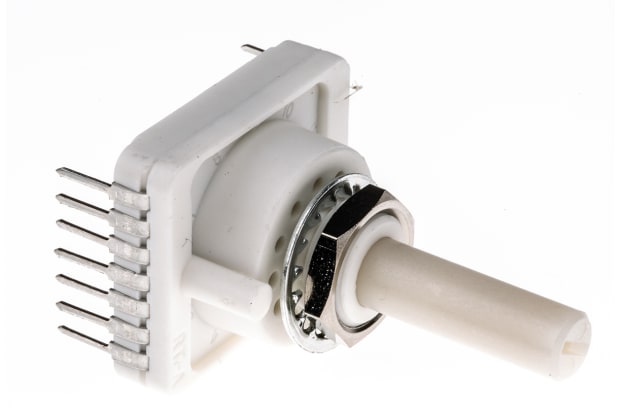
How Does a Rotary Switch Work?
Let’s look at how rotary switches work. Despite the different designs and configurations available, they all have the same fundamental design - a spindle or rotor with a protruding spoke. As the spindle revolves within its shaft, the spoke moves into different positions, contacting the electrical terminal in each and activating the attached circuits or changing an electrical state (e.g. from on to off). These circuits travel through a circular component called a wafer. Multiple circuits may be attached to a single position.
Most rotary switches feature a rotor with a notched or star wheel design rather than a smooth surface as this discourages stalling in an intermediate position between the terminals or contact points. A spring-loaded mechanism called a detent may also be installed for the same purpose.
The terminals are typically positioned around the spindle at set rotational intervals - usually 30, 45, 60 and 90 degrees. These angles determine the number of switch positions available.
The number of user-selectable positions can be limited in some rotary switches through the insertion of a washer into specially designed slots - converting, for example, a 12-position switch into a four-position one if that is all that is required.
How to Wire a Rotary Switch
The following is a guide to basic rotary switch wiring:
- Identify the primary 1 output point for each input terminal. They may be labelled but if not, rotate the switch into the 1 position and then use an Ohmmeter to detect the flow of current
- Get the wire ends ready - either stripping the insulation back by around ¼ of an inch for soldering or by attaching an appropriate connector
- Apply the incoming device wire to the rotary switch input terminal by soldering or pressing the connector into place. If your rotary switch has more than one input terminal, repeat this process for each
- Finally, again using either solder or a connector, attach the outgoing wires to the correct output terminals. The first device or circuit in order of operation should be attached to the 1 terminal, and the second device or circuit connected to the next, moving in a clockwise direction
Popular Brands
RS PRO
Explore the full range of rotary switches available from RS PRO, our own in-house line of quality products.
Lorlin
With an extensive range of products available, click through to shop Lorlin rotary switches from RS.
TE Connectivity
With a wide range of different features and configurations available, TE Connectivity are sure to have a rotary switch to meet your needs.
C&K
Click through to view the full range of C&K rotary switches and shop online with RS today.
Rotary Switch Types
There are many different types of rotary switch. Here are some of the most widely-used:
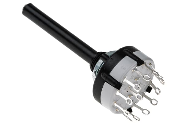
Wafer Switches
Wafers are components in most rotary switch models that distribute electricity from the spindle to the output terminals. Rotary wafer switches are a special design in which contacts are arranged on both sides of the wafer.
Yaxley Switches
Yaxley switches are a traditional rotary switch design, now little used.
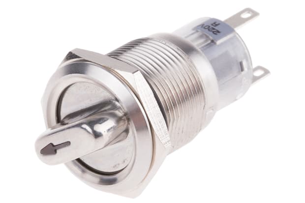
Miniature Rotary Switches
Mini rotary switches are designed for use in settings where space is at a premium, for example, circuit boards. Typically, they are fully open or fully closed and often used as sensors to detect the position of other parts.
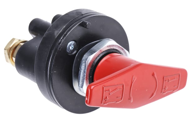
High Current Rotary Switches
High current rotary switches are specially designed for higher voltages. They are made from materials resistant to electrical discharge such as ceramics and both the casing and contact points are reinforced.
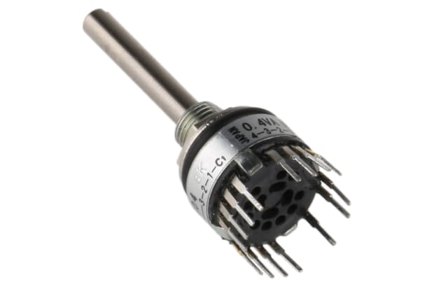
Rotary Cam Switches
Rotary cam switches feature a shaft that increases or decreases electrical resistance in the attached contact points when turned. They are a good choice for electronic instruments with variable currents.
Rotary DIP Switches
Rotary DIP switches are groups of switches aligned in a dual in-line package, a standard configuration typically used on printed circuit boards and in other electronic components. Also known as dual-in-line (DIL) switches, they are used to adjust the electrical response of the device in which they are installed.
Binary Rotary Switches
Binary rotary switches are another miniaturised design for use in delicate electronic equipment. They use a binary on-off system.
Momentary Rotary Switches
Momentary rotary switches are used in a variety of electrical circuits to provide a momentary change of state function, such as switching from one circuit to another or from on to off. A momentary switch returns to a default position after being pressed.
PCB Mount Rotary Switches
PCBs mount rotary switches are upright controls mounted on printed circuit boards (PCBs). They are used to control multiple output terminals.
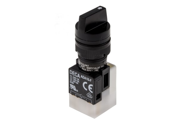
Heavy-Duty Rotary Switches
Heavy-duty rotary switches are designed to provide robust mechanical control in demanding industrial environments.
Available rotary switch accessories and add-ons include:
- Replacement dials, caps and knobs
- Rotating open circuits
- Shaft assemblies and spindles
- Lock mechanisms
Contact Configuration - Poles, Positions & Ways
Contact points in an electrical circuit are called terminals. The electrical entry point - or input terminal - on a rotary switch is called a pole, and some designs feature more than one, each connecting via rotation to a series of output terminals, called ways. Most rotary switches feature 3-way, 4-way, 6-way or 12-way configurations, but higher numbers are available. The switching position - the point at which a switch interacts with a circuit - is called a throw.
Different configurations of rotary switches have different combinations of poles, ways and throws. Some of the most common include:
- Double pole double throw (DPDT) rotary switches. Two on-on switches which work in conjunction
- Double pole four throw (DP4T) rotary switches. These are widely used in radios, TVs, home lighting systems and industrial settings
- 8-pole rotary switches. This widely used design offers an easily selectable choice of input terminals or poles
- 2-pole 2-position rotary switches. In this rotary switch design, the dual poles are connected to the two selectable positions
- 2-pole 6-position rotary switches. In this design, each pole is wired to three selectable positions
- Multi-pole rotary switches. Standard rotary switch designs feature a single pole. Multi-pole models offer greater versatility
- Double pole three throw (DP3T) rotary switches. In this design, two separate circuits intersect at three different points, providing three selectable switch positions